UAE Fire Protection System Design Guidance
Fire protection systems in the United Arab Emirates are governed by the UAE Fire & Life Safety Code of Practice issued by Civil Defence authorities to ensure the safety of occupants, protection of property, and continuity of building operations during fire emergencies. These guidelines outline the fundamental design principles for systems such as automatic sprinklers, wet and dry risers, fire hydrants, hose reel networks, fire pumps, and specialized suppression systems based on occupancy hazard classification and building characteristics. The purpose of this section is to provide a practical technical overview of key fire protection requirements commonly applied in UAE projects to support architects, developers, and engineers during planning and coordination stages. Detailed system design should always be carried out in accordance with the latest Civil Defence approved regulations and project-specific approval requirements.
UNITS
Fire protection system design commonly uses a combination of SI and non-SI units for pressure, volume, and flow calculations. Understanding these units helps ensure correct interpretation of hydraulic requirements and coordination with international fire protection standards such as NFPA and UAE Civil Defence practices.
Pressure
-
1 bar = 14.5 psi
-
1 psi = 0.0689 bar
Volume
-
1 US gallon = 3.785 liters
-
1 liter = 0.264 US gallons
-
1 cubic meter = 1000 liters
-
1 cubic meter = 264.17 US gallons
Flow
-
1 gallon per minute (GPM) = 3.78 liters per minute (LPM)
These units are widely used in sprinkler hydraulics, fire pump sizing, storage tank calculations, and hydrant system design.
Hazard Classification for Sprinkler Protection

Fire Hose Systems (Class I, II & III)

Fire Hose System Classification (Typical Applications)

Fire Pump Requirements (Typical UAE Civil Defence Practice)

Typical Vertical Turbine Fire Pump Arrangement (Concept Illustration – NFPA 20 / UAE Practice)
Typical Vertical Turbine Fire Pump Arrangement – Concept illustration based on NFPA 20 design practice. Final configuration shall comply with UAE Civil Defence requirements.

Typical Horizontal Fire Pump Arrangement (NFPA 20 / UAE Practice Concept Illustration)
Typical Horizontal Fire Pump Arrangement – Concept illustration based on NFPA 20 design practice. Final installation shall comply with UAE Civil Defence requirements.

Minimum Fire Pump Pipe Size Guidance (NFPA 20)
Pipe sizes summarized from NFPA 20 guidance commonly adopted in UAE fire pump design practice. Final sizing shall comply with Civil Defence approval requirements.

Fire water tank arrangements shall comply with UAE Fire & Life Safety Code requirements and Civil Defence authority approvals. Table above summarizes common design provisions used in practice.

Isolation / Section Control Valves

Check Valves

Dry Riser Systems (Typical UAE Civil Defence Practice)

Fire Hose Reel Systems (Typical UAE Civil Defence Practice)

Combined Dry Riser and Hose Reel System Arrangement (Typical UAE Practice)

Wet Riser Systems
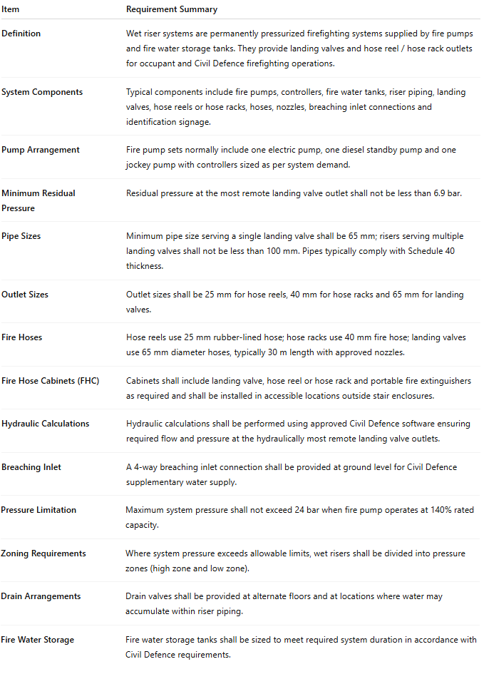
Typical Fire Hose Cabinet Location Requirements

Typical Wet Riser Systems
