Design of Water Supply Distribution System
An efficient plumbing system starts with a design that saves water and energy resources. A good design incorporates short runs between plumbing fixtures and uses state-of-the art materials. A plumbing design must include two systems: the system that supplies water and the system that gets rid of waste. Before you begin designing a house for plumbing, drain, waste and vent systems, you must follow local building codes to ensure design compliance.
A Plumbing designer should know the basic plumbing principles and standards of plumbing materials. Avoid any plumbing plans that requires the plumber to weaken the building structure.
Distribution System for a Building: Water is conveyed from the street mains to the individual building, and then to the taps and other fixtures. The supply from the main line to the individual is made through the house service connection.

Materials
(a) All pipe, tube, and fittings carrying water used in potable water system intended to supply drinking water shall meet the requirements of NSF 61 as found in Table 14-1.
(b) Materials for building water piping and building supply piping shall be in accordance with Table 6-4 (UPC) and Table 3-4 (NSPC).


PP-R Pipes
CPVC Pipes
PEX Pipes
Pipe Identification:
(a) Potable Water : Green background with white lettering
(b) Non-Potable Water: Yellow background with black lettering, with the words " Caution: Non-Potable water, do not drink".
Backflow Prevention:
(a) When a backflow occurs, it can pollute entire water systems. Without a backflow and back siphonage protection, municipal water services could become contaminated.
(b) Backflow prevention can be done using Airgap, Atmospheric Vacuum Breaker (AVB), Hose connection backflow preventer, Double check valve backflow prevention assembly(DC), Pressure vacuum breaker backflow prevention assembly (PVB) etc.
(c) An air gap is the most positive form of protection from backflow.

Air Gap Backflow Preventer
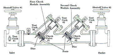
Double Check Valve Backflow Preventer
Atmospheric Vacuum Breaker
Water closet and urinal flushometer valves shall be equipped with an atmospheric vacuum breaker. The vacuum breaker shall be installed on the discharge side of the flushometer valve with the critical level at least 6".


Ballcock
Water closet and urinal tanks shall be equipped with a ballcock. The ballcock shall be installed with the critical level at least 1" above the full opening of the overflow pipes.

Separation of Water Service and Building Sewer
The water service pipe and building drain shall not have less than one foot horizontal distance between the piping.

Water Service Near Source of Pollution
Potable water service piping shall not be located in, under, or above septic tanks or drainage pits. A separation of 10 feet shall be maintained from such systems. When a water line parallels or crosses over or under a sewer, a minimum clearance of 12 inches in all directions shall be maintained.
Flushing
The water service piping and distribution piping to all fixtures and outlets shall be flushed until the water runs clear and free of debris or particles. Faucet aerators or screen shall be removed during flushing operations.
Disinfection
Water service piping and the hot and cold water distribution piping in new or renovated potable water systems shall be disinfected after flushing and prior to use. The procedure used shall be as follows or an approved equivalent:
Procedure:
-
Flush all pipes with clean water.
-
Dose with sodium hypochlorite (≈50 mg/L initially).
-
Hold 1–2 mg/L residual chlorine for 1 hour at outlets.
-
Flush again till chlorine ≈0.2–0.5 mg/L.
-
Collect samples and send to DM-approved lab for bacteriological tests (Total Coliform, E. coli = 0).
Tanks:
-
Disinfect with 20 mg/L chlorine for 1 hour, then flush.
Building Valve (Isolation Valve)
The building water service shall be provided with a readily accessible Gate Valve. When there are two or more water services serving one building, a check valve shall be installed on each service in addition to the above valves.

Pressure Reducing Valves
Where static water pressure in the water supply piping is in excess of 80 psi (552 kPa), an approved type pressure reducing valve by an adequate strainer shall be installed and the static pressure reduced to 80 psi or less.


Hose Connection
A pressure type or atmospheric type vacuum breaker or a permanently attached hose connection vacuum breaker shall protect hose bibs, sill-cocks, wall hydrants opening with a hose connections.


Stop-and-Waste Valve Prohibited
Combination stop-and-waste valve or cocks shall not be installed underground in water serving piping.
Water Service Pipes Sleeves
Pipe sleeves shall be provided where water services pipes penetrate foundation walls or floors. Slab to be protected against corrosion of pipe and allow clearance for expansion, contraction and settlement. The annular space between the pipe and the sleeve shall be resiliently sealed watertight.

Water Pressure Booster Systems
(a) When the water pressure in the public water main or individual water supply system is insufficient to supply the potable peak demand flow to plumbing fixtures and continuously with minimum pressure, the rate of supply shall be supplemented by one of the following:
1. An elevated water tank
2. An hydro-pneumatic pressure booster system
3. A water pressure booster pump.

Water Tanks
A water tower is an elevated structure supporting a water tank constructed at a height sufficient to pressurize a water distribution system for the distribution of potable water .
Water towers are able to supply water even during power outages, because they rely on hydrostatic pressure produced by elevation of water (due to gravity ) to push the water into domestic and industrial water distribution systems; however, they cannot supply the water for a long time without power, because a pump is typically required to refill the tower. A water tower also serves as a reservoir to help with water needs during peak usage times. The water level in the tower typically falls during the peak usage hours of the day, and then a pump fills it back up during the night. This process also keeps the water from freezing in cold weather, since the tower is constantly being drained and refilled.


Pressurized Water Tanks
A pressure tanks creates water pressure by using compressed air to bear down on water. When a valve is opened, water is pushed out by the compressed air in the tank. The water is pushed throughout the plumbing in the house until the pressure drops to a preset low on pressure switch. All pressurized water tanks should be equipped with a vacuum relief valve at the top of the tank. These vacuum relief valve shall be rated for maximum temperature of 200° F and maximum pressure of 200 psi.
It is also necessary to equip these tanks with pressure-relief valves. These safety valves must be installed on the supply pipe that feeds the tank or on the tank, itself.


A Water Pressure Booster Pump
A booster pump increases low water pressure and flow. It provides the extra boost needed to bring your water pressure to the desired level. A water booster pump provides pressure to move water from a storage tank or throughout a whole house or commercial facility.
Booster pumps increase low water flow in water systems or industrial equipment and transport water from a lake, pond, or storage tank for use in a home or commercial building. A household that doesn't receive enough pressure from the city water supply would need a pump to increase low water pressure. A hotel needs a large commercial booster pump to send water all the way to the top story.
A booster pump is also used to re-pressurize water from a storage tank and send it to a faucet or throughout a home. In a rain harvesting system, for example, water collects in a storage tank. In order to use it to flush toilets or wash laundry, the water must be pumped out of the tank and into the house. You would use a booster pump to move the water.


Water Hammer
Water hammer in a pipeline is caused by a sudden stoppage of flow and is characterized by loud noise and vibration. The formula expressing the relationship between pressure.
All building supply systems in which quick-acting valves are installed shall be provided with devices to absorb the hammer caused by high pressure resulting from the quick closing of these valves. Water pressure absorbing devices shall be installed as close as possible to quick acting valves.


Valve Regulations
Gate and ball valves are examples of full open valves as required under valve regulations. These valves may be required in the following locations:
a. On the water service before and after the water meter.
b. On each water service for each building served.
c. On discharge pipes of water supply tanks near the tank.
d. On the supply pipe to every water heater near to the heater.
e. On the main supply pipe to each dwelling / toilets.
f. On water supplies to pressurized tanks, such as well system

Hot Water Supply System
a) In residences and building intended for human occupancy, hot water shall be supplied to all plumbing fixtures and equipment's used for bathing, washing, laundry or building maintenance.
b) If the distance between the hot water source and the fixture being served is more than 100 feet, a re-circulating system is required.

Hot Water Storage Tanks
a) Water heaters and storage tanks shall be sized to provide sufficient hot water to provide both daily requirements and hourly peak loads of the occupants of the buildings.
b) Storage tanks shall be protected against excessive temperature and pressure conditions.
c) Hot water storage tanks shall be equipped with a valve capable of draining the tank completely.


FAQs on Water Supply System Design
1. What is the purpose of a water supply system in a building?
A water supply system ensures safe and reliable delivery of potable water to all plumbing fixtures (sinks, showers, toilets, laboratories, firefighting systems, etc.). It includes service connections, distribution piping, storage, valves, and controls.
2. How is water supplied to a building?
Water is usually supplied from the municipal main or a storage tank. It enters the building through a house service connection equipped with stopcocks, valves, and meters. The supply is then distributed through rising mains, branch lines, and final fixture connections.
3. What is a backflow prevention device and why is it important?
Backflow preventers, such as vacuum breakers or check valves, stop contaminated water from flowing back into the clean water supply. Plumbing codes require them especially where water outlets may be submerged or exposed to contamination.
4. What is the minimum installation height for a vacuum breaker?
A vacuum breaker must be installed at least 12 inches (300 mm) above the floor or ground level. This ensures proper functioning and prevents siphonage of contaminated water into the potable system.
5. What types of valves are used in water supply design?
Common valves include:
-
Gate Valve – for isolation, fully open/close control.
-
Globe Valve – for throttling/flow regulation.
-
Check Valve – to prevent reverse flow.
-
Butterfly Valve – for compact shut-off in large pipes.
-
Relief/Safety Valve – to protect against overpressure.
6. How are water distribution branch lines arranged?
Branch lines are connected to mains in a way that ensures balanced pressure and flow. Codes recommend odd/even spacing of connections and avoiding excessive dead-ends. Looping branch lines improves circulation and reduces stagnation.
7. How are water supply pipes sized?
Pipe sizing depends on fixture unit load, flow demand, pressure, and pipe material. Each plumbing fixture has a defined water supply fixture unit (WSFU). The total demand determines the pipe diameter to maintain adequate flow and pressure.
8. Where should flow meters be installed in water supply systems?
Flow meters must be installed in straight pipe runs without bends, valves, or turbulence near the meter. Proper placement ensures accuracy in measuring water usage for billing or monitoring.
9. How is corrosion controlled in water supply systems?
Corrosion is mitigated using sacrificial anodes (cathodic protection), protective coatings, and corrosion-resistant pipe materials (e.g., copper, PEX, CPVC, stainless steel). Regular maintenance helps extend system life.
10. How is water supply design coordinated with plumbing and fire fighting systems?
Water supply must be integrated with plumbing (fixtures, drainage) and fire fighting (sprinklers, hydrants, pumps). Designers ensure adequate pressure, prevent pipe clashes in service shafts, and include shut-off and bypass arrangements for system reliability.
11. What is the role of overflow pipes in water supply systems?
Overflow pipes are installed in storage tanks, cisterns, and reservoirs to prevent flooding in case the inlet valve fails. They are usually connected to a safe discharge point and sized large enough to handle the maximum inflow rate.
12. How is hot water distribution designed differently from cold water distribution?
Hot water distribution requires:
-
Insulated pipes to reduce heat loss.
-
Recirculation loops in large buildings to maintain temperature.
-
Mixing valves at fixtures for scald protection.
Cold water design focuses mainly on pressure balance and supply reliability.
13. What are test cocks in a backflow preventer assembly?
Test cocks are small valves installed on backflow prevention devices (like double check valve assemblies and vacuum breakers). They allow inspectors or plumbers to test the device for leaks, proper function, and pressure differences during routine maintenance.
14. How is operating pressure determined in a water supply system?
Operating pressure depends on:
-
Municipal supply pressure or pump capacity.
-
Building height (static head requirements).
-
Fixture demand and pipe friction losses.
Typical operating pressures range from 40–80 psi (2.7–5.5 bar). Pressure-reducing valves are used if supply pressure is too high.
15. What is the difference between direct and indirect water supply systems?
-
Direct system: Water from the municipal main directly supplies all fixtures.
-
Indirect system: Water first fills storage tanks (overhead or underground) and is then distributed by gravity or pumps.
Indirect systems are more common in multi-storey buildings to ensure consistent pressure.