Hydraulic Calculations for Fire Fighting System
Join YouTube Channel "Design Fire Protection with Kamal Ram"
We designing a fire protection system, hydraulic calculations are very important to ensure that the flow rate in piping network will be enough to control fires effectively. In NFPA, the calculation procedures are established and verified by the three basic elements of firefighting system:
-
Water delivery requirements of fire sprinkler system
-
Available water supply
-
The piping network system and its related friction losses.
Occupancy Classification
Any hydraulic design of sprinkler systems must begin with an analysis of the commodity being protected. The National Fire Protection Association, Standard No. 13 “Installation of Sprinkler Systems” (NFPA-13) defines three basic commodity classification: Light Hazard, Ordinary Hazard and Extra Hazard. These classifications are defined in NFPA-13 and examples are given in that document. Ordinary Hazard occupancies are divided into two categories: Ordinary Hazard Group 1 and Ordinary Hazard Group 2. Extra Hazard occupancies are also divided into two categories: Extra Hazard Group 1 and Extra Hazard Group 2. Once a hazard classification is chosen for a known occupancy, the water requirements may be established from NFPA-13, (2007) Figure 11.2.3.1.1
Density/ Area Curve for water requirements
NFPA-13, (2007) Figure 11.2.3.1.1 displays five density/area curves overlain on a graph. These five curves correspond to the previously discussed hazard classifications: Light Hazard, Ordinary Group 1 Hazard, Ordinary Group 2 Hazard, Extra Hazard Group 1 and Extra Hazard Group 2. These curves stipulate the required minimum densities and remote areas that establish minimum water requirements for sprinkler systems.

Densities and Remote Areas
These curves stipulate the required minimum densities and remote areas that establish minimum water requirements for sprinkler systems.
Density - The amount of water that must be delivered every minute for every square foot of floor space. The English units for density is (gallons per minute per square foot (gpm/sq.ft.) For example, a Light Hazard occupancy could be designed for a density of 0.1-gpm/sq.ft. This means that 0.1-gallons must discharge every minute for every square foot of floor space over a specified area.
Remote Area – the minimum area of floor space over which the density must discharge.
As an example, Figure 11.2.3.1.1 indicates that an acceptable design for an Ordinary Hazard Group 1 occupancy is 0.15-gpm/sq.ft. over 1500-sq.ft.
This means the sprinkler system designer will choose the most hydraulically demanding 1500-sq.ft. of the sprinkler system layout and perform a calculation of all sprinklers within that 1500-sq.ft. area. Therefore, only a portion of sprinklers on a sprinkler system are expected to operate during a typical fire, not all. If all sprinklers on a sprinkler system operate the water supply most likely will not be adequate to control the fire.
Calculating number of sprinklers in Remote Area
Total number of sprinklers = Remote Area (Design Area) / Area covered by one sprinkler.
For example, if Remote area = 1500 sq-ft and area covered by one sprinkler = 130 sq -ft
Total number odd sprinklers = 1500/130 = 11.538.
Therefore, we shall consider 12 Nos. of sprinklers which the water tank must provide for sprinklers to operate in case of fire.
End sprinkler start conditions
Once the hydraulic requirements are selected for the occupancy, the hydraulic calculation of the sprinkler system may begin. In modern times sprinkler system hydraulics are performed by computer programs. However, in the early days of sprinkler system hydraulic design all systems were calculated with a calculator as we will do here. A thorough understanding of these principles is not required to perform calculations on a hydraulic calculation program but these are the principles on which the program operates. A better understanding of these principles will allow the designer to better understand how the sprinkler system will function hydraulically. The density/area curves will tell the designer the starting point of the design. Our example is an Ordinary Hazard Group 1 occupancy and we will choose the point on the density/area curve of 0.15- gpm/sq.ft. over 1500-sq.ft.
This means that every square foot of the 1500-sq.ft. remote area must be covered with at least 0.15- gpm. By extension, this means that the floor area under each sprinkler, called the Protection Area of Coverage, must be provided with 0.15-gpm/sq.ft. In other words, each sprinkler must discharge enough water to provide a minimum of 0.15-gallons per minute for every square foot it protects.

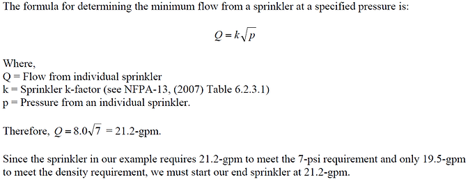
The end sprinkler must discharge 19.5-gallons every minute over the 130-sq.ft. it protects in order to meet the minimum density requirement of NFPA-13. We might start the calculation process at this point, however there is one other item that must be verified. NFPA-13, (2007) section 22.4.4.10.1 states that no sprinkler may operate at less than 7-psi. This means that we must verify that our end sprinkler satisfies this condition. For our example, we have chosen a sprinkler with a k-factor of 8.0.
Formula used in Hydraulic Calculation process


Manual Sprinkler Hydraulic Calculations — Step by Step
Project Description
This project involves the hydraulic calculation of an automatic wet-pipe sprinkler system for a commercial building. The system has been designed in accordance with NFPA 13 standards, with reference to Ordinary Hazard (Group 1) occupancy criteria.
Before starting the step-by-step hydraulic calculation, it is essential to establish the preliminary design steps that form the basis of any manual calculation:
-
Select the Remote Area: Identify the hydraulically most remote area of the system as per NFPA 13 (or relevant standard). This area must represent the most demanding portion of the sprinkler network, typically at the highest elevation and farthest distance from the water supply.
-
Define Design Criteria: Fix the design density, coverage area, hazard classification, sprinkler K-factor, temperature rating, and required duration. For example, in this project the system is classified as Ordinary Hazard – Group 1 with 0.15 gpm/ft² over 1500 ft² using pendent sprinklers (K5.6, 68 °C).
-
Prepare the Isometric Diagram: Using AutoCAD (or equivalent drafting software), draw the sprinkler piping in isometric form. Clearly mark all nodes, elevations, pipe sizes, lengths, and fittings as these will serve as input for the hydraulic calculation. Each node should correspond to a junction, sprinkler, or change in elevation/pipe size.
-
Assign Node Numbers & Pipe References: Number the sprinklers, tees, and junctions consistently (e.g., S1–S14 for sprinklers, numeric labels for tees/nodes). This numbering will be used in the calculation sheet and later matched against the computer model (HASS, Elite, or other).
-
Verify Input Data: Ensure that the isometric diagram, pipe lengths, and equivalent lengths for fittings are checked against the design drawings. This prevents discrepancies between manual calculations and software outputs.
By completing these preparatory steps, the manual hydraulic calculation becomes systematic: the remote area is correctly defined, the isometric is clear, and all necessary inputs are ready before pressure and flow calculations begin.


DESIGN DATA:
Remote Area Location: Mezzanine Floor
System Type: Wet System
Hazard: Ordinary Hazard
Design Density: 0.15 gpm/ sq. ft
Remote Area: Maximum: 1500 SQ. FT
Sprinkler Classification: Pendent Area
Maximum Sprinkler Coverage: 130 sq. ft
Sprinkler K-Factor: K5.6
Sprinkler Temp Rating : 68 deg C
CALCULATING END SPRINKLER FLOW IN REMOTE AREA
Design Density = 0.15 gpm/sq ft
Maximum area covered by one sprinkler = 130 sq. ft
Flow required at end sprinkler = 0.15 x130 gpm
= 19.5 gpm
CACLULATING END SPRINKLER PRESSURE
Using equation.
Q = K x √P
Where, Q = Flow in gpm (gallons per minute)
K = Sprinkler constant given by manufacture data sheet
P = Pressure at sprinkler in psi (pound per square inch)
Once the flow (Q) is calculated, the required pressure (P) can be calculated by simply rearranging the above formula:
P
Q = 19.5 gpm
K = 5.6
Therefore, Pressure required at end sprinkler = (19.5/5.6)^2 = 12.12 psi.
Therefore, our calculation shall start at Pressure P = 12.12 psi.
Formulas used in fire protection hydraulic calculations
1) Sprinkler Discharge Formula

2) Density–Area Method (NFPA 13)

3) Hazen–Williams Friction Loss

4) Elevation (Static Head) Loss/Gain

5) Water Velocity in Pipe

6) Velocity Pressure

Determine the number of operating sprinklers in the remote area


Hydraulic Calculations – HASS Software
The following pages present the hydraulic calculation results generated using HASS software for the sprinkler and hydrant system of DLYFT INDIA LLP.
These calculations have been performed in compliance with NFPA 13 requirements, using the Hazen–Williams method (C = 120 for new steel pipe). The HASS program evaluates the entire piping network simultaneously, accounting for:
-
Actual pipe sizes, lengths, and elevations as modeled.
-
Equivalent lengths of fittings (tees, elbows, valves) automatically included per NFPA 13 tables.
-
Elevation changes (0.433 psi/ft) across all nodes.
-
Sprinkler discharge determined by the K-factor and operating pressure (Q = K√P).
-
Pressure/flow balance at each junction node, ensuring conservation of flow.
The output provides node analysis data (pressure and discharge at each sprinkler) and pipe-by-pipe friction loss, velocity, and demand summary, enabling verification that the system demand is satisfied by the available water supply.
Here is HASS Input:

The HASS hydraulic calculation confirms that the sprinkler and hydrant system design meets the required NFPA 13 criteria.
-
All remote sprinklers achieve the minimum required discharge density and pressure.
-
System losses—including pipe friction, fitting equivalent lengths, and elevation differences—have been fully accounted for.
-
Node pressures at the most remote points remain above the required minimum (≥ 7 psi at sprinklers).
-
The total system demand (sprinkler + hose allowance) is satisfied by the available water supply curve with adequate safety margin.
-
Flow velocities in piping remain within acceptable ranges, minimizing risk of water hammer or excessive pressure loss.
Therefore, the modeled system is hydraulically balanced, code-compliant, and supported by the available water supply.
Difference Between Manual and HASS Results
The variation between manual hydraulic calculations and the HASS software output is expected, because of the way each method treats the system:
-
Manual calculation is usually simplified:
-
Starts each remote head at a fixed pressure (e.g. 12 psi).
-
Considers only straight pipe friction and basic elevation terms.
-
Fittings (tees, elbows, valves) are often omitted or added selectively.
-
Each branch is checked independently, then combined.
-
-
HASS calculation is more comprehensive:
-
Solves the entire network simultaneously, balancing pressures and flows at all nodes.
-
Applies equivalent length losses for every fitting automatically from NFPA 13 tables.
-
Assigns true sprinkler discharge (Q = K√P) based on the actual pressure at each head.
-
Includes elevation, velocity, and demand analysis consistently for all pipes.
-
Result: HASS pressures are generally higher at intermediate nodes than manual estimates, and friction losses are larger, because the program includes all fitting losses and realistic pressure balancing. Manual calcs are good for understanding the process, but HASS output is the accepted reference for design approval.
Fire Hydraulic Calculations Basis of Design
As per NFPA 14-7.10.1.1.1, For Classes I and III systems, the minimum flow rate for the hydraulically most remote standpipe shall be 500 gpm. Also as per NFPA 14, 7.10.1.1.3, the minimum flow rate of additional standpipe shall be 250 gpm per standpipe with the total not to exceed 1250 gpm or 1000 gpm for buildings sprinklered throughout. Also as per NFPA 14 section 7.8, the residual pressure required at the most demanding Landing Valve is 100 psi.
It should be noted that when providing the above requirements for a Combined System (Sprinkler and Landing Valves on the same standpipe), there is no need to add the sprinkler demand as per NFPA 14-7.10.1.3.
Based on above, 500 gpm for one standpipe and add 250 gpm for two other standpipe.
Thus, the minimum total flow required by NFPA 14 is 1000 gpm.


Click here for....
Hydraulic Calculations – FAQs
Q1. Why are hydraulic calculations required?
To verify that the fire protection system (sprinklers, standpipes, hydrants) delivers adequate flow and pressure under worst-case demand.
Q2. What software/tools are acceptable for Civil Defence submission?
-
HASS, Elite, AutoSPRINK (licensed).
-
NFPA-compliant hand/Excel methods may also be accepted.
Q3. What is the hydraulic safety factor required?
-
Minimum 10% safety margin between supply and demand curve.
Q4. How is system demand curve developed?
-
Plot flow vs. pressure for sprinklers + hose + hydrants.
-
Compare with water supply curve (pump curve + tank).
Q5. What documents are required for Civil Defence review?
-
Hydraulic calculation summary sheet.
-
Demand vs. supply curves.
-
Node-by-node pressure analysis.
-
Head loss tables.
Q6. What standards are calculations based on?
NFPA 13, NFPA 14, and UAE Fire & Life Safety Code Chapter 9.
Q7. What allowances must be considered in calculations?
-
Hose stream allowance:
-
250 gpm for sprinklers.
-
500 gpm for standpipe.
-
-
Hydrant allowance: 2 × 63 mm outlets at 100 psi.
Q8. How is elevation head calculated?
10 m elevation ≈ 1 bar pressure loss.
Q9. What formula is used for pipe friction loss?
Hazen–Williams formula (C-factor 120 for steel, 150 for CPVC).
Q10. What is the required base of riser pressure?
Sufficient to meet pressure at hydraulically most remote point, considering friction + elevation.
Q11. What are Civil Defence submittal requirements for hydraulic calcs?
-
Input data (hazard classification, design density, coverage area).
-
Calculation summary sheet.
-
Node-by-node pressure report.
-
Demand vs. supply graph.
Q12. What are common mistakes leading to Civil Defence rejection?
-
Not including hose allowance.
-
Not considering elevation properly.
-
Demand > supply curve (negative safety margin).
-
Wrong C-factor values.
Q13. How are tank sizing calculations verified?
By ensuring pump demand × required duration (60 min for sprinklers, 90 min for hydrants) = net tank volume.
Q14. What is the approval process?
Civil Defence reviews drawings, calcs, and test certificates before granting approval.