Fire Pump Design
NFPA 20: Standard for the Installation of Stationary Pumps for Fire Protection protects life and property by providing requirements for the installation of fire pumps to ensure that systems will work as intended to deliver adequate and reliable water supplies in a fire emergency.
A fire sprinkler system is a critical component of life safety in a building. The International Building Code grants a number of exceptions when a building is “fully sprinklered,” such as reductions in rated separations, reductions in fire hydrant flow demands, increased egress travel distances and increased building heights and areas. These exceptions are permitted with an expectation that, in the event of a fire, the sprinkler system will suppress the fire to a sufficient degree that occupants can safely evacuate the building and the growth of the fire will be controlled until the fire department arrives to fully extinguish it.
Often, the municipal water system has sufficient pressure to operate the sprinkler system. A fire pump is required when the available water source does not have adequate pressure. When a sprinkler system relies on a fire pump, the performance of the system is dependent on the pressure created by the pump.
Because of the critical importance of the fire pump, careful consideration should be employed when selecting and designing a fire pump. Fire pumps are a critical component of a building's sprinkler system in settings where the water supply is insufficient to provide the pressure needed to keep the water flowing to all the sprinkler heads. Fire pump intakes are connected to underground public water supply piping, or a tank or reservoir located onsite, to provide water flow at a higher pressure to the sprinkler system risers and hose standpipes.


Sizing a Fire Pump
A fire pump’s size is dictated by the most hydraulically demanding area of the fire protection system. In many high-rise buildings, this can be the automatic fire standpipe system demand which requires 500 gallons per minute at 100 pounds per square inch at the top of the most remote standpipe, plus 250 gpm for each additional standpipe, up to a maximum of 1,000 gpm for wet systems or 1,250 gpm for dry systems.
For example, a new sprinkler system might be installed in a five-story medical office building with a partial basement (overall building height of 69 feet). The building construction is noncombustible, Type II-B and each floor is approximately 18,000 square feet. The basement level contains electrical rooms, general storage rooms, a small oxygen storage room (250 square feet) enclosed by a two-hour fire rating and a covered exterior loading dock.
The most hydraulically demanding area in this example is the level five mechanical room. Though the density for this remote area is only 0.15 gpm (ordinary hazard group 1), the top floor location requires additional pressure to overcome the head loss from elevation. The remote area size is increased to 1,950 square feet due to a 30% increase for slopes exceeding 2:12 (NFPA 13-2013, Section 11.2.3.2.4). The estimated flow demand for this area is approximately 380 gpm (0.15 gpm x 1,950 square feet = 292.5 gpm + 30% for sprinkler head overflow = 380 gpm). A preliminary hydraulic calculation indicates a required system pressure of 90 psi.
Selecting the Fire Pump
Once you have calculated the gpm and psi requirements for the pump, you need to determine the type of pump that works best for the job. The three most widely used pumps are horizontal split case, inline and vertical turbine.
Horizontal split case pumps are also called double-suction fire pumps, because the water pathways direct water to both sides of the impeller. They are the most common type of fire pump on the market, partly because of the ratings available in this style of pump, typically 250 through 5,000 gpm. This was the first type of pump used for fire protection systems.
Vertical turbine pumps are used in situations where the water supply is below the suction flange of the fire pump, because NFPA 20 requires a positive suction pressure to a fire pump.
The other item that needs to be determined is the type of drive: diesel or electric. Once that is determined, you can find the appropriate pump model and horsepower in a manufacturer’s catalog. I don’t recommend using pump curves to select fire pumps, as every selection must be UL approved, which might lead to picking the wrong horsepower for a particular selection.
One other note on fire pump selection is that selecting pumps that have a higher rpm is not necessarily a misstep, because fire pumps only run once a week for a limited amount of time, so the length of life will be about the same for a 1,750 rpm pump as for a 3,500 rpm pump.

Water Supplies
Any source of water that is adequate in quality, quantity and pressure shall be permitted to provide the supply for a fire pump.The available flow at the fire pump discharge at the lowest permissible suction pressure shall be a minimum of 100 percent of rated flow.
Maximum Pressure for Centrifugal Pumps
The net pump shutoff(churn) pressure plus the maximum static pressure, adjusted for elevation, shall not exceed the pressure for the system components are rated. Pressure relief valves and pressure regulating devices in the fire pump installation shall not be used as a means to meet the requirements.
Centrifugal Fire Pump Capacities
A centrifugal fire pump for fire protection shall be selected so that the greatest single demand for any fire protection system connected to the pump is less than or equal to 150 percent of the rated capacity (flow) of the pump.
Centrifugal fire pumps shall have one of the rated capacities in gpm (L/min) identified in Table 4.10.2 and shall be rated at the net pressures of 40 psi (2.7 bar) or more.

Pressure Gauges
A pressure gauge having a dial not less than 3.5 inch (89 mm) in diameter shall be connected near the discharge and suction side with a nominal 0.25 inch (6 mm) gauge valve. The dial shall indicate pressure to at least twice the rated working pressure of the pump but not less than 200 psi (13.8 bar).

Circulation Relief Valve
Excessive heat in the pump can cause severe damage in a short period of time causing pump bearings to fail - as the bearings' lubricants typically degrade twice as fast for each 10 degrees Celsius rise in temperature - while seals and packing begin to leak. In more extreme cases, the rise in temperature can cause the water to flash to vapor and cause cavitation damage to the impeller and pump internals.
To avoid this damage, we must lower the temperature of the water being churned in the pump casing or housing. This can be achieved by allowing a small amount of cooler water into the pump casing.
For all fire pump systems, except those using a cooling line to a diesel engine driven pump, a circulation relief valve should be fitted in order to extract heated water from the pump's discharge. This valve should be fitted between the pump discharge side and the outlet control valve. This circulation relief valve should be set to open at the pump unit shutoff pressure plus the minimum pump suction pressure. It should allow a relatively small amount of hot water to constantly flow out of the pump casing, which is then replaced by an equal amount of cool unheated water entering the pump through the suction side, thus cooling the pump and its casing.


The automatic relief valve have a nominal size of 3/4 inch (19 mm) for pumps with a rated capacity not exceeding 2500 gpm and have a nominal size of 1 inch (25 mm) for pumps with a rated capacity of 3000 gpm to 5000 gpm.
Circulating relief valve requirements shall not apply to engine-driven pumps for which engine cooling water is taken from the pump discharge.
Fire Pump Buildings or Rooms with Electric Drivers
Fire pump buildings or rooms enclosing diesel engine pump drivers and day tanks shall be protected with an automatic sprinkler system installed in accordance with NFPA 13 as an "Extra Hazard Group 2 occupancy".

Fire Pump Buildings or Rooms with Diesel Engine
For buildings that are required to be sprinklered, fire pump buildings or rooms enclosing electric fire pump drivers shall be protected with an automatic sprinkler system installed in accordance with NFPA 13 as an "ordinary hazard Group 1 occupancy".
Suction Pipe and Fittings
Suction pipe shall be galvanized or painted on the inside prior to installation with a paint recommended for submerged surfaces.
Sections of steel piping shall be joined by means of screwed, flanged mechanical grooved joints or other approved fittings.
The piping around check valves, orifice unions, orifice plates, flowmeters and other devices that have restricting orifices shall have a means to perform an internal inspection or a means to disassemble the piping to allow for the internal inspections.
Suction pipe size shall be such that, with all pumps operating at maximum flow (150 percent of rated capacity or the maximum flow available from the water supply at the lowest permissible suction pressure), the gauge pressure at the pump suction flanges shall be 0 psi or higher.
Where supply is from a suction tank with its base at or above the same elevation as the pump, the gauge pressure at the pump suction flange shall be permitted to drop to -3 psi at 150 percent of rated flow with the lowest water level after the maximum system demand and duration have been supplied.


Anti-Vortex Plate
Where a tank is used as the suction source for a fire pump, the discharge outlet of the tank shall be equipped with an assembly that controls vortex flow in accordance with NFPA 22.
ANTI-VORTEX PLATE IS INSTALLED IN THE SUCTION LINE OF FIRE PUMPS TO CONTROL THE TURBULENCE IN A FLOWING WATER, THEY ARE SIMPLE IN DESIGN AND VERY EFFECTIVELY CONTROLLING THE VELOCITY OF THE FLUID THUS PREVENTING CAVITATION TO FIRE PUMPS AND DAMAGE TO IMPELLERS.


Pressure Relief Valve
Pressure relief valve (Fire pump relief valve / safety valve) is used in the discharge of fire pump to automatically relieve excessive pressure, so to maintain constant pressure. It allows the fire pump to be stopped without causing surging.


A Pressure Relief Valve is defined by NFPA 20 (3.3.67.5 Relief Valve) as “A device that allows the diversion of liquid to limit excess pressure in a system.”
In general, a PRV is a safety device, designed to protect a pressurized system during an overpressured event. An overpressured event refers to any condition which would cause pressure in a system to increase beyond the specified design pressure or maximum allowable working pressure. Since Pressure Relief Valves are safety devices, there are many codes and standards written to control their design and application.
For Centrifugal Pumps, the NFPA 20 (4.19.1.2) requires that “a Pressure Relief Valve shall be installed. where a diesel engine fire pump is installed and where a total of 121 percent of the net rated shutoff (churn) pressure plus the maximum static suction pressure, adjusted for elevation, exceeds the pressure for which the system components are rated.”
A Pressure Relief Valve is required by the standard to be installed when the diesel engine is turning faster than normal, because the pressure is proportional to the square of the speed that the pump is turned. This is a relatively rare event; if pumps create pressures less than the pressure rating of the fire protection system components [typically 175 psi (12.1 bar)] at 110 percent of rated speed, a Pressure Relief Valve is not required.


The standard specifically does not permit the use of a main pressure relief valve on an electric fire pump, except where a variable speed driver is used. Variable speed drivers are required to default to constant rated speed operation. In the event the variable speed driver fails, the rated speed can result in system over-pressurization. In this case a pressure relief valve is required.
When designing a fire pump, it is highly important that the designer match the pump to the system demands, in order to avoid overpressurizing the system and then using pressure regulating devices to compensate.
Pressure Maintenance (Jockey or Make-Up) Pumps
A jockey pump is a small pump connected to a fire sprinkler system to maintain pressure in the sprinkler pipes. This is to ensure that if a fire-sprinkler is activated, there will be a pressure drop, which will be sensed by the fire pumps automatic controller, which will cause the fire pump to start.
A jockey pump is sized for a flow less than the flow to one sprinkler in order to ensure a system pressure drop. The function of jockey pumps is an important part of the fire pumps control system.
Jockey pumps are typically small multi-stage centrifugal pumps, and do not have to be listed or certified for fire system application. The control equipment for jockey pumps may however carry approvals.

Summary of Centrifugal Fire Pump Data


A packaged fire pump assembly, with or without an enclosure, shall meet all of the following requirements:
-
The components shall be assembled and affixed onto a steel framing structure.
-
Welders shall be qualified in accordance with the Section 9 of ASME Boiler and Pressure Vessel Code or with the American Welding Society AWS D1.1, Structural Welding Code — Steel.
-
The total assembly shall be engineered and designed by a system designer as referenced in 4.3.2 (NFPA 20,2019).
-
All plans and data sheets shall be submitted and reviewed by the authority having jurisdiction, with copies of the stamped approved submittals used in the assembly and for record keeping.

Fire Pump Test Arrangement
Where the water supply to a fire pump is a tank, a listed flowmeter or test header discharging back into the tank with a calibrated nozzle(s) arranged for the attachment of a pressure gauge to determine pitot pressure shall be required.


A diesel fire pump needs a Venturi-type flowmeter primarily for accurate measurement of flow rate during pump testing and operation. Here’s why:
(a) High Accuracy and Reliability: Venturi flowmeters provide precise and consistent measurements of flow rates. This accuracy is critical for ensuring that the fire pump is delivering the required water flow as per design specifications, which is vital in emergency situations.
(b) Low Pressure Drop: The design of a Venturi flowmeter minimizes pressure loss in the system. This is important in fire protection systems because maintaining adequate pressure is essential to ensure that water reaches all parts of the fire suppression system effectively.
(c) Durability and Low Maintenance: Venturi flowmeters have no moving parts, making them more durable and less prone to wear and tear. This is especially important in fire protection systems, where equipment must be reliable and ready to operate during emergencies.
(d) Compliance with Standards: Many fire protection standards, such as those from NFPA (National Fire Protection Association), often require or recommend the use of accurate flow measurement devices like Venturi flowmeters to ensure the system meets performance criteria during testing and commissioning.
Using a Venturi-type flowmeter in a diesel fire pump setup ensures that the system operates efficiently, safely, and within regulatory compliance.
Automatic Air Release Valve
Air release valve is used in wet pipe sprinkler systems and on casing of horizontal split case pump, so to to automatically release small pockets of accumulated air while the system operates under pressure exceeding atmospheric pressure.
A nominal 1.5 in (38 mm) pipe size or larger automatic air release valve shall be provided to vent air from the column and discharge head upon the starting of the pump.
This valve shall also admit air to the column to dissipate the vacuum upon stopping of the pump.
This valve shall be located at the highest point in the discharge line between the fire pump and discharge check valve.

Pressure Sensing Line
The sensing line is connected to the fire protection system between its respective pump discharge check valve and the discharge control valve (E and F). The size of the sensing lines shall be a minimum of ½-inch and must be of non-corrosive metallic pipe or tube (brass, copper, stainless steel).
-
Both fire pump and jockey pump sensing lines are piped exactly the same with separate connections.
-
Non-ferrous material is used for the sensing line (bronze, stainless, or copper).
-
Both lines have 2 orifices drilled into check valves at least 5 feet apart
-
Size of the orifice in check valves is 3/32 inch
-
Arrows on check valves point away from the control panel
-
Size of sensing lines are ½”
-
Jockey pump is installed on the high pressure side of the fire pump piping.
-
Fire pump is installed on the high pressure side of the fire pump piping.
-
A ¾” casing relief valve has been installed on the discharge side of the fire pump before the fire pump check valve.
-
The direction of the arrow on the casing relief valve is pointing towards the drain.


Diesel Engine-Driven Fire Pump Systems
A fire pump can be driven by an electric motor, diesel engine or steam drive. While electric motors are most common, steam drives are infrequently utilized. Diesel engines are often used when the electrical supply to the property is unreliable or has insufficient capacity. They also are used by clients who desire a primary electric motor-driven fire pump system and a redundant diesel engine-driven fire pump system or used in a property requiring a redundant system due to its seismic zone or height.
For all fire pump applications, diesel engines must be “listed” for the fire pump system application. Typical listing agencies for diesel drivers are UL and FM Global. Listed fire pump engines are provided by companies such as Caterpillar, Clarke Fire Protection Products and Cummins. These companies are responsible for ensuring the diesel engine is suitable for fire protection services.

DIESEL FIRE PUMP ROOM COMPONENTS
A diesel fire pump room is a critical component of a fire protection system, housing the diesel engine-driven fire pump and various supporting equipment. Here’s a list of the key components typically found in a diesel fire pump room:
1. Diesel Fire Pump:
-
Purpose: The main component, driven by a diesel engine, responsible for pumping water from a water source (e.g., a tank, reservoir, or water mains) into the fire protection system at the required pressure.
-
Types: There are different types of fire pumps, such as horizontal split-case, vertical turbine, and vertical inline, depending on the system design.
2. Diesel Engine:
-
Purpose: Provides the mechanical power required to operate the fire pump.
-
Components: Includes the engine block, fuel system, cooling system, lubrication system, exhaust system, and air intake system.
-
Starting Methods: Typically includes batteries for electric start and an air or hydraulic starting system as a backup.
3. Fuel System:
-
Fuel Tank: Stores the diesel fuel needed to operate the engine, sized to allow the engine to run for a minimum of 8 hours.
-
Fuel Piping: Connects the fuel tank to the engine.
-
Fuel Filters: Ensures that clean fuel is supplied to the engine by removing impurities.
4. Cooling System:
-
Purpose: Cools the engine to prevent overheating during operation.
-
Heat Exchanger: Transfers heat from the engine coolant to the raw water used for cooling.
-
Radiator (if applicable): In some configurations, a radiator may be used instead of a heat exchanger.
-
Cooling Water Pump: Circulates water through the engine and heat exchanger.
5. Exhaust System:
-
Purpose: Safely vents exhaust gases produced by the diesel engine.
-
Components: Includes an exhaust manifold, muffler, and exhaust piping, which should be routed to the outside of the building.
6. Control Panel:
-
Purpose: Monitors and controls the operation of the diesel engine and fire pump.
-
Components: Includes start/stop controls, engine status indicators, alarms, and safety shutdowns.
-
Auto Start Functionality: Automatically starts the diesel engine upon receiving a signal from the fire detection system or loss of electrical power.
7. Batteries:
-
Purpose: Provide the power needed to start the diesel engine.
-
Battery Charger: Keeps the batteries fully charged and ready for use at all times.
8. Jockey Pump:
-
Purpose: A small pump that maintains system pressure and prevents the fire pump from starting due to minor pressure drops.
-
Location: Installed in the same room or nearby, with its own control panel.
9. Relief Valve:
-
Purpose: Protects the pump and piping from over-pressurization by releasing excess pressure.
-
Location: Typically installed on the discharge side of the fire pump.
10. Flow Meter:
-
Purpose: Measures the flow rate of water through the pump during testing and operation.
-
Location: Usually installed on the test line, which is separate from the main fire protection piping.
11. Test Header (Flow Test Connection):
-
Purpose: Allows for periodic testing of the fire pump to ensure it meets the required flow and pressure.
-
Components: Consists of a series of outlets or nozzles where hoses can be connected to discharge water during testing.
12. Engine Cooling Water Discharge:
-
Purpose: The cooled water from the engine is typically discharged into a drain or back to a water source, depending on the system design.
13. Ventilation System:
-
Purpose: Ensures proper air circulation to remove engine heat and supply fresh air for combustion.
-
Components: Includes intake and exhaust vents, fans, and louvers.
14. Room Lighting:
-
Purpose: Provides sufficient lighting for operation and maintenance tasks.
-
Emergency Lighting: Battery-powered or connected to an emergency power source to ensure visibility during power outages.
15. Floor Drain:
-
Purpose: Allows water or fuel spills to drain safely out of the room, preventing flooding and damage to equipment.
16. Soundproofing (Optional):
-
Purpose: Reduces noise levels from the diesel engine, especially important in buildings where noise control is necessary.
17. Fire Extinguishers:
-
Purpose: Provides immediate fire suppression capability within the pump room itself, typically ABC type or CO2 extinguishers.
18. Alarm and Monitoring System:
-
Purpose: Alerts operators to critical conditions, such as engine failure, low fuel levels, or high temperatures.
-
Components: Connected to the building’s fire alarm system and sometimes to a remote monitoring station.
19. Emergency Shutdown System:
-
Purpose: Allows the pump to be shut down in case of an emergency or malfunction.
20. Signage:
-
Purpose: Provides clear instructions and labels for operating procedures, emergency shutdowns, and safety information.
Each component plays a vital role in ensuring the diesel fire pump operates reliably when needed during an emergency. Proper installation, testing, and maintenance of these components are essential for the system's overall effectiveness.
Fuel Supply and Arrangement
NFPA 20 requires a dedicated listed fuel tank located aboveground under municipal or other ordinances, and per the requirements of the authority having jurisdiction. In areas subject to freezing, the tank must be located in the fire pump room. It is required to have a dedicated fill, vent(s), and a visual and monitored fuel level gauge installed.

In the marketplace today, two types of fuel tanks are available: single- and double-wall tanks. While a single-wall tank is initially less expensive, a full tank capacity spill-containment system must be provided. A double-wall tank, by design, includes the spill containment device. Its containment space must be monitored for leakage from the inner wall. Vents from interstitial spaces of double-wall tanks may not be manifolded together with a vent from the primary compartment of the tank.
The minimum capacity of the fuel tank is driven by a simple equation: 1 gallon per rated horsepower plus 5 percent for sump and 5 percent for expansion. While you should install a fuel tank of at least minimum size, providing too large of a tank is not necessarily a better idea. Diesel fuel has a shelf life and there are requirements for periodic fuel-quality testing.

Engine Exhaust
A proper exhaust system is required to dispose of all combustion gasses safely. It must be routed to a safe place of discharge; design and installation must be in accordance with the engine’s manufacturer’s installation manual, NFPA 20, municipal or other ordinances, and per the requirements of the authority having jurisdiction.
Sizing of the exhaust system needs to be completed by a calculation program to ensure the back pressure on the diesel engine complies with the listing. The type of silencer selected, the size and length of the pipe run, the number and type of fittings, and other factors will all impact the minimum pipe size required.


Fire Pump Controller
In simple terms, a fire pump controller is a device to reliably start and stop a fire pump, as well as monitor conditions in an ongoing manner that could hinder or prevent the proper operation of a fire pump. They act the same way any motor controller operates, except they are built with more strict standards to ensure that the priority is protecting a property and its occupants over the fire pump motor (or engine) itself.
UL and FM both “list” or “approve” fire pump controllers. This listing ensures that all fire pump controllers, regardless of manufacturer, all contain specific elements and design to ensure reliable operation in the event of a fire. The minimum required components of fire pump controllers are governed by NFPA 20

Fire pump controllers can be manually used to start fire pumps, either through use of a button switch, or lever on the controller. But most commonly, fire pump controllers are set up to operate automatically, either by a drop in system pressure in a sprinkler system, or via a signal from a remote device, such as a flow switch or deluge valve. Each controller also can be set up to run continuously until manually shut off, or a timer can be used to automatically stop the fire pump after a set amount of time has transpired (assuming the pressure in the system has stabilized).
Once started, a fire pump controller can be set to automatically reset, or (more commonly) require a manual stop, whereby someone has to manually push a button on the controller to stop it.


Fire Pump start and stop settings
1. Jockey Pump Stop Point:
-
Formula: Jockey Pump Stop Point = Pump Churn Pressure + Minimum Static Supply Pressure
-
The jockey pump should stop at a pressure equal to the pump churn pressure (the pressure when the pump is running with no flow) plus the minimum static supply pressure. This ensures that the system pressure is maintained at an optimal level.
2. Jockey Pump Start Point:
-
Formula: Jockey Pump Start Point = Jockey Pump Stop Point - 10 psi (0.68 bar)
-
The jockey pump should start at a pressure that is at least 10 psi (0.68 bar) less than the jockey pump stop point. This drop in pressure typically occurs due to minor system leaks or small demands, which the jockey pump is designed to handle.
3. Fire Pump Start Point:
-
Formula: Fire Pump Start Point = Jockey Pump Start Point - 5 psi (0.34 bar)
-
The fire pump should start when the system pressure drops 5 psi (0.34 bar) below the jockey pump start point. This ensures that the fire pump only operates when there is a significant demand on the system, such as multiple sprinklers activating during a fire.
-
For Multiple Pumps: Use a 10-psi (0.68-bar) increment for each additional pump, ensuring that subsequent pumps start at a lower pressure than the first. This staggered start helps prevent water hammer, which can damage the system.
4. Fire Pump Shut Off:
-
Manual Shut Off: The fire pump must be shut off manually once it is started. This is a safety measure to ensure the pump continues to provide water during an emergency until the situation is under control and the system can be safely turned off.
5. Consideration for Pressure Switches:
-
Adjustments: If the pressure switches on the system do not allow for the exact settings as described, the settings should be as close as possible based on the equipment’s capabilities. Test gauges should be used to establish these settings accurately.
These guidelines are designed to ensure that the fire protection system remains ready to respond to emergencies, maintaining the appropriate pressure levels and preventing unnecessary wear on the equipment.
Example:
Pump: 1000-gpm, 100-psi pump with churn pressure of 115 psi.
Suction Supply: 50 psi from city — minimum static. 60 psi from city — maximum static.
Jockey pump stop = 115 + 50 = 165 psi.
Jockey pump start = 165 - 10 = 155 psi.
Fire pump stop = 115 + 50 = 165 psi.
Fire pump start = 155 - 5 = 150 psi.
Fire pump maximum churn = 115 + 60 = 175 psi.
Hydrostatic Tests and Flushing
Flushing
Suction piping shall be flushed at a flow rate not less than indicated in Table 14.1.1.1 or at the hydraulically calculated water demand rate of the system, whichever is greater.
Flushing shall occur prior to hydrostatic test.
Where the maximum flow available from the water supply cannot provide the flow rate provided in Table 14.1.1.1, the flushing flow rate shall be equal to or greater than 150 percent of rated flow of the connected fire pump.
Where the maximum flow available from the water supply cannot provide a flow of 150 percent of the rated flow of the pump, flushing flow rate shall be greater of 100 percent of the rated flow of the connected fire pump or the maximum flow demand of the fire protection system.

Hydrostatic Test
Suction and discharge piping shall be hydrostatically tested at not less than 200 psi (13.8 bar) pressure or rated 50 psi (3.4 bar) in excess of the maximum pressure to be maintained in the system, whichever is greater.
The pressure shall be maintained for 2 hours.
The installing contractor shall furnish a certificate for flushing and hydrostatic test prior to the start of the fire pump field acceptance test.
Field Acceptance Tests
The pump manufacturer, the engine manufacturer (when supplied), the controller manufacturer, and transfer switch manufacturer (when supplied) or their factory authorized representatives shall be present for the field acceptance test.
Explanatory Materials as per NFPA 20-2019


FIRE PUMP FORMULAS


Fire Pump Testing & Commissioning Procedure (NFPA 20)
1. Pre-Commissioning Checks
-
Verify pump installation matches approved drawings and NFPA 20 requirements.
-
Inspect suction/discharge piping, strainers, valves, gauges, relief valves, and test headers.
-
Check alignment between pump and driver (electric motor/diesel engine).
-
Inspect lubrication, cooling, exhaust system, and batteries (diesel).
-
Verify controller wiring, alarms, ATS, and sensing lines.
-
Ensure water supply (tank/municipal) is ready and clean.
2. Initial Start-Up
-
Start pump manually at the controller to confirm correct rotation and smooth operation.
-
Record suction, discharge, and net pressures.
-
Observe vibration, noise, and overheating.
-
Shut down and recheck alignment and couplings.
3. Performance Testing (NFPA 20 §14.2.6)
NFPA 20 requires pumps to be tested at several points along their performance curve:
-
Churn Test (0% flow):
-
Run pump with discharge valve closed.
-
Record suction/discharge/net pressures.
-
Verify circulation relief valve operation.
-
-
-
Rated Flow (100%):
-
Flow water through test header/flow meter to rated GPM.
-
Record pressures, RPM, motor current, or diesel fuel parameters.
-
Verify pressure meets manufacturer’s curve.
-
-
-
Overload Flow (150% of rated):
-
If water supply allows, increase flow to 150% rated.
-
Ensure pressure ≥65% of rated.
-
-
-
Intermediate Flow Points:
-
NFPA 20 also requires testing at one or more intermediate points (e.g., 50% rated flow).
-
4. Automatic and Manual Operation
-
Verify manual start/stop at the controller.
-
Test automatic start by:
-
Simulating pressure drop.
-
Activating remote alarm signal.
-
Simulating power failure (for diesel/electric).
-
-
Confirm jockey pump maintains system pressure under normal conditions.
5. Safety & Integration Testing
-
Test pressure relief valve operation (if installed).
-
Verify circulation relief valve flows at churn.
-
Simulate loss of power (for electric) and low fuel/battery faults (for diesel).
-
Test signals for alarms:
-
Pump running
-
Phase reversal
-
Controller fail
-
Battery fail
-
Low fuel
-
6. Endurance & Reliability
-
Run pump at rated load for 1 hour minimum.
-
For diesel: demonstrate 8-hour fuel supply.
-
Inspect for leaks, overheating, or electrical overloads.
-
Military/aviation sites may require multiple start cycles (10–20) to prove reliability.
7. Acceptance & Documentation
-
Record results in a tabular test sheet (flow, suction/discharge pressures, RPM, amps, etc.).
-
Plot actual performance curve vs. certified pump curve.
-
Submit commissioning report including:
-
As-built drawings
-
Calibration certificates
-
Test sheets
-
AHJ sign-off forms
-
Fire Pumps – FAQs
Q1. What is the minimum fire pump arrangement required?
-
1 Electric Pump
-
1 Diesel Pump
-
1 Jockey Pump
Q2. What if reliable dual power supply is available?
Two electric pumps + 1 jockey pump may be allowed (with Civil Defence approval).
Q3. What is the role of a jockey pump?
Maintains system pressure, prevents main pump from frequent start/stop.
Q4. What is the requirement for pump capacity?
-
As per hydraulic demand (sprinkler + hose reel/standpipe + hydrant).
-
Must meet most demanding system curve with 10% safety margin.
Q5. What are Civil Defence approval requirements for pumps?
-
UL/FM or Civil Defence–listed.
-
Installed in dedicated fire pump room with ventilation, drainage, and fire rating.
-
Separate power source for diesel pump.
Q6. How should pump testing be conducted?
-
Weekly jockey and main pump test.
-
Annual full flow test.
-
Test header connections provided.
Q7. What are the pump starting sequence requirements?
-
Jockey pump starts first.
-
Electric/diesel main pump starts if pressure drops further.
-
Auto-changeover between pumps.
Q8. What is the maximum suction lift allowed?
Fire pumps must be flooded suction type.
Suction lift not permitted except with vertical turbine pumps.
Q9. What are the tank-to-pump suction pipe requirements?
-
Two independent connections from tank.
-
Min. 2 × 100% capacity pipes.
-
Isolation valves with locked-open position.
Q10. What is the acceptance test requirement?
Full flow test through test header to verify pump curve.
Q11. What is the emergency power requirement?
-
Diesel engine pumps must have 8 hrs fuel storage.
-
Separate battery chargers & starting batteries.
Q12. What instrumentation is required on pumps?
-
Suction/discharge pressure gauges.
-
Flow meter/test header.
-
Pump room annunciator panel.
Q13. What is the temperature control for pump room?
Maintain ≥10°C for diesel pump operation.
Q14. What is the inspection/maintenance schedule?
-
Weekly: jockey & main pump run.
-
Monthly: pump house inspection.
-
Annual: full flow test witnessed by Civil Defence.
15. What is the purpose of a fire pump?
A fire pump boosts water pressure and flow for fire protection systems (sprinklers, standpipes, hydrants) when the municipal supply or onsite tank cannot meet demand.
16. Which standard governs fire pump installation?
NFPA 20: Standard for the Installation of Stationary Pumps for Fire Protection (2019 edition) covers pump types, drivers, controllers, suction/discharge piping, testing, and installation requirements.
17. What types of fire pumps are commonly used?
-
Centrifugal Pumps – horizontal split-case, end suction, vertical inline, vertical turbine.
-
Positive Displacement Pumps – foam concentrate, water mist, additive pumps.
-
Drivers – electric motor, diesel engine, steam turbine.
18. What is a jockey pump and why is it important?
A jockey (pressure maintenance) pump keeps the system pressurized under minor leaks or thermal expansion, preventing unnecessary starting of the main fire pump.
19. What are the approval requirements?
All pumps, drivers, and controllers must be listed/approved by a recognized testing laboratory (Sec. 4.2).
20. How is pump performance verified?
-
Factory test (Sec. 4.5): Certified shop test curve at churn, 100%, and 150% rated flow.
-
Field acceptance test (Sec. 4.34): Must match certified curves within NFPA tolerances.
21. What are the suction piping requirements?
-
Straight length ≥ 10 pipe diameters before suction flange.
-
Use eccentric reducer (flat on top).
-
Avoid elbows directly at suction.
-
Backflow preventer, if required, must be on the discharge side.
22. When is a circulation relief valve required?
-
Required for centrifugal pumps to prevent overheating at churn (Sec. 4.13).
-
Not required for:
-
Vertical shaft turbine pumps with suction from an open wet pit/unlimited source.
-
Diesel-driven pumps where cooling water is taken from the pump discharge (Sec. 4.13.1.8).
-
23. What are the valve supervision requirements?
All suction, discharge, bypass, and auxiliary valves must be supervised in the open position (Sec. 4.18).
24. How does NFPA 20 address seismic protection?
Seismic bracing, anchoring, and flexible couplings are required in earthquake zones (Sec. 4.30).
25. Can pumps be installed in series?
Yes. NFPA 20 (Sec. 4.21) allows pumps in series if the first pump takes suction from the supply and subsequent pumps handle elevated zone pressures.
26. What are the pump room requirements in high-rises?
-
Rooms must be fire-rated, accessible, ventilated, and protected from flooding/freezing (Sec. 5.2).
27. Are dedicated test headers required?
Yes. High-rises require external pump test headers accessible to the fire department (Sec. 5.4).
28. What about water supply tanks?
Must comply with NFPA 22. Tanks for high-rises often have refill valves, zoning, and dual compartments (Sec. 5.3).
29. Is alternate power mandatory in high-rises?
Yes. Alternate power (generator or dual utility feed) is required to ensure reliability (Sec. 5.5).
30. How does NFPA 20 define very tall buildings?
For very tall buildings (Sec. 5.6):
-
Automatic refill valves are mandatory.
-
Multiple pumps in series or zoning may be required.
-
Redundancy and dual power supplies are strongly emphasized.
Q31. Why is fire pump testing and commissioning important?
Testing and commissioning verify that the installed fire pump performs as designed under actual operating conditions. It ensures that the pump delivers the required flow and pressure, starts automatically during fire conditions, and complies with NFPA 20 requirements before handing over the system to the client.
Q32. What tests are performed during fire pump commissioning?
Typical tests include:
-
Visual and Pre-Functional Checks (alignment, suction/discharge piping, valves, strainers).
-
No-Flow (Churn) Test (pump performance without flow).
-
Flow Test (at 100%, 150%, and shutoff conditions).
-
Automatic & Manual Start Tests (verifying controller response).
-
Alarm & Shutdown Verification (power failure, phase reversal, low fuel, etc.).
-
Endurance Run (usually 1–2 hours at rated load for diesel pumps).
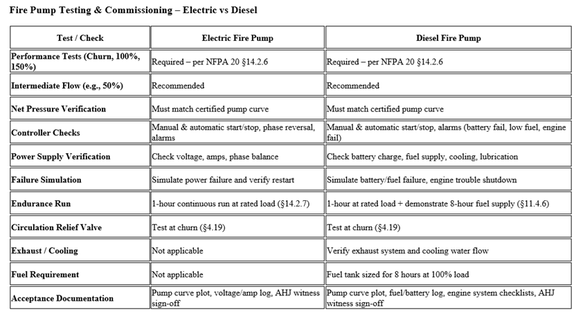
Q33. Are the tests different for electric and diesel fire pumps?
The flow test procedure is the same for both. However, diesel fire pumps have additional requirements such as battery inspection, fuel system checks, cooling system verification, and ensuring reliable multiple starts. Some authorities (e.g., US Army Corps of Engineers projects) mandate 10 manual + 10 automatic start attempts during commissioning for diesel pumps.
Q34. How long does a fire pump commissioning test take?
A complete commissioning session usually takes half a day to one full day depending on pump type (electric or diesel), flow testing arrangements, and site conditions.
Q35. Who is responsible for witnessing and approving the test?
Commissioning is typically witnessed by:
-
Owner’s representative or consultant
-
Authority Having Jurisdiction (AHJ) (such as Civil Defense, NFPA enforcement authority)
-
Fire Protection Engineer (FPE) for technical verification
Q36. What documents are provided after successful commissioning?
The commissioning team provides:
-
Pump performance test report (flow vs. pressure curve)
-
Controller functional test records
-
Diesel engine test records (if applicable)
-
Signed commissioning certificate confirming compliance with NFPA 20
Q37. What is a “churn test” and why is it important?
A churn (or shutoff) test is conducted with no water flowing from the pump discharge. It ensures the pump develops the required shutoff pressure without overloading the driver and that there are no leaks or vibrations.
Q38. How is a fire pump flow test conducted?
The flow test is performed by flowing water through hose valves, test headers, or flow meters to simulate fire demand. Measurements are taken at 100% rated flow, 150% rated flow, and churn to verify the pump curve against the manufacturer’s certified test curve.
Q39. Does NFPA 20 require endurance or reliability testing?
Yes. Diesel fire pumps are required to undergo a continuous run test (typically 2 hours) to confirm engine cooling, fuel system reliability, and overall endurance under actual load. Electric pumps may also undergo a prolonged run if required by the AHJ.
Q40. What safety checks are verified during commissioning?
-
Low suction pressure alarm
-
Phase reversal/phase loss (electric pumps)
-
Battery charger failure (diesel pumps)
-
Fuel level, oil pressure, coolant temperature alarms
-
Automatic transfer between primary and backup power (if applicable)
Q41. How often should fire pumps be retested after commissioning?
Once commissioned, NFPA 25 requires:
-
Weekly/monthly no-flow (churn) test
-
Annual flow test (at churn, 100%, and 150% capacity)
-
Diesel engine weekly exercise to verify battery and starting reliability
Q42. What happens if the pump fails during testing?
If the fire pump does not meet NFPA 20 requirements, corrective actions must be taken — such as adjusting alignment, repairing valves, or replacing faulty components — followed by a re-test in the presence of the AHJ before acceptance.
Q43. Do all fire pumps require flow meters for commissioning?
Not necessarily. NFPA 20 allows either a permanent flow meter or a test header with hoses/nozzles to measure flow during commissioning and annual testing. Many sites use hose valves and pitot gauges for cost efficiency.
Q44. Who maintains the fire pump after commissioning?
After handover, the maintenance team/facility management assumes responsibility under NFPA 25, performing periodic inspections, runs, and flow tests to ensure long-term readiness.