Standpipe (Fire Hose Reel) System
A standpipe system is defined by NFPA 14 as: “An arrangement of piping, valves, hose connections and allied equipment installed in a building or structure, with the hose connections located in such a manner that water can be discharged in streams through attached hose and nozzles, for the purposes of extinguishing a fire, thereby protecting a building or structure and its contents in addition to protecting the occupants. This is accomplished by means of connections to water supply systems or by means of pump tanks and other equipment necessary to provide an adequate supply of water to the hose connections (NFPA, 2003).”


Automatic Standpipe System:
A standpipe system that is attached to a water supply capable of supplying the system demand at all times and that requires no action other than opening a hose valve to provide water at hose connections.
Combined System:
A standpipe system having piping that supplies both hose connection and automatic sprinkler system.
High Rise Building:
A building more than 75 feet (23 m) in height. Building height shall be measured from the lowest level of fire department vehicle access to the floor of the highest occupiable story.
Manual Standpipe System:
A standpipe system that relies exclusively on the fire department connection to supply the system demand.

Classes of Standpipe System
Class I System:
Class I Standpipe system shall provide 2-1/2 in (63.5 mm) hose connections to supply water for use by fire department and hose trained in handling heavy fire streams. Canvas hose is generally carried by Fire Department.
Class II System:
Class II Standpipe system shall provide 1-1/2 in (38.1 mm) hose stations to supply water for use primarily by the building occupants or by the fire department during initial response.
Class III System:
Class III Standpipe system shall provide 1-1/2 in (38.1 mm) hose stations to supply water for use by building occupants and 2-1/2 in (63.5 mm) hose connections to supply a larger volume of water for use by fire departments and hose trained in handling heavy fire streams.


Location of Hose Connections
Class I Standpipe system shall be provided 2-1/2 in (63.5 mm) hose connections in the following locations:
a) At each intermediate landing between floor levels in every required exit stairways.
b) On each side of the wall adjacent to the exit openings of horizontal exits.
c) In each exit passageway at the entrance from the building areas into the passageway.
d) In covered mall buildings, at the exterior to each exit passageway or exit corridor, and at exterior public entrances to the mall.
Class II systems shall be provided with 1-1/2 in (38.1 mm) hose stations so that all portions of each floor level of the building are within 130 ft (39.7 m). Distances shall be measured along a path of travel originating at the hose connections.


Minimum Sizes of Standpipes
a) Class I and Class III standpipes shall be at least 4 in (102 mm) in size.
b) Standpipes that are part of a combined system shall be at least 6 in (152 mm ) in size.

Minimum Pressure for System Design and Sizing of Pipe
Hydraulically designed to provide the required waterflow rate at a minimum residual pressure of 100 psi (6.9 bar) at the outlet of the hydraulically most remote 2-1/2 in (63.5 mm) hose connection and 65 psi (4.5 bar) at the outlet of the hydraulically most remote 1-1/2 in (38.1 mm ) hose station.

.png)

Maximum Pressure for Hose Connections
Where the residual pressure at 1-1/2 in (38.1 mm) outlet on a hose connection available for occupant use exceeds 100 psi (6.9 bar), an approved pressure regulating device shall be provided to limit the residual pressure to 100 psi (6.9 bar).

Minimum Flow Rates
(a) For class I and class III systems, the minimum flow rate for the hydraulically most remote standpipe shall be 500 gpm (1893 L/min. The minimum flow rate for additional standpipes shall be 250 gpm ( 946 L/min) per standpipe, with total not to exceed 1250 gpm (4731 L/min).
(b) For a combined system in a building equipped with partial automatic sprinkler protection, the flow rate required shall be increased by an amount equal to the hydraulically calculated sprinkler demand or 150 gpm (568 L/min) for light hazard occupancies, or 500 gpm (1893 L/min) for ordinary hazard occupancies, whichever is less.
(c) For class II systems, the minimum flow rate for hydraulically most remote standpipe shall be 100 gpm (379 L/min). Additional flow shall not be required where more than one standpipe is provided.


%20Typical%20SIngle%20Zone%20Syste.png)
%20Typical%20Two%20Zone%20Systen_p.png)
%20Typical%20Multi%20Zone%20Systen.png)
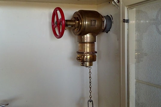
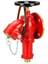
Landing Valve (LV)
Landing Valve. Landing valves are suitable for installation on wet risers in buildings for fire fighting purposes, permanently charged with water from a pressurized supply. They are Globe valves that are installed on hydrants, a branch and hose is connected to a coupling on it.
(a) Size : 2 -1/2 in
(b) Outlet : Female instantaneous to BS 336
(c) Minimum Pressure Required : 65 PSI (4.5 Bar)
(d) Maximum Pressure Allowed at LV : 100 psi (6.9 Bar)
(e) Flow at Landing Valev : 250 GPM
(f) Lanlding Valve K-Factor : 31
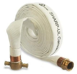
Canvas Hose
(a) Size 1-1/2 in for Class II
(b) Size 2-1/2 in for Class I & III
(c) Length of Hose : 30 Mtr
(d) Branch pipe (Nozzle ) : 2-1/2 in male instantaneous connection
(e) Branch pipe postion : OFF / JET / FOG
Standard Fire Hose Reel Cabinet
Components of Fire Hose Cabinet:
1) Fire Hose Reel 25mm dia x 30 Mtr
2) Gate Valve 25 mm
3) PRV 25 mm
4) 9L Water/Gas Type Fire Extinguishers
5) 6 Kg ABC Fire Extinguishers
6) Landing Valve 2-1/2 in
7) Canvas Hose 1-1/2 in x 30 Mtr


Fire Hose Reel and Standpipe System – FAQs
Q1. What is a fire hose reel system?
A fixed firefighting system comprising hose reels located within buildings to provide occupants with immediate water for fire control during the early stages.
Q2. What are the standpipe system classes?
-
Class I – 65mm landing valve for fire brigade use.
-
Class II – 25mm hose reel for occupant use.
-
Class III – Combined (both 25mm hose reels + 65mm hydrant connection).
Q3. What are the design pressures for hose reels/standpipes?
-
Hose reel: 6 bar at outlet with 30m length.
-
Landing valve: minimum 100 psi (7 bar) at 2.5” (65mm).
Q4. Where are hose reels required?
-
Every floor of buildings >500 m² floor area.
-
Travel distance to nearest hose reel ≤30 m.
Q5. What is the requirement for breeching inlets?
-
Provided at fire service access point.
-
Civil Defence pumper connection to supplement system.
Q6. What are the types of standpipe systems?
-
Class I – 65 mm landing valve (FD use).
-
Class II – 25 mm hose reel (occupant use).
-
Class III – Combined system.
Q7. Where should hose reels be located?
At each floor exit lobby or corridor such that travel distance ≤30 m.
Q8. What is the minimum pipe size for standpipe riser?
-
100 mm for combined risers.
-
150 mm for high-rise and where demand exceeds 500 gpm.
Q9. How many hose reels should be connected to one riser?
Max. 12 reels per riser (unless hydraulically justified).
Q10. What is the minimum residual pressure required at breeching inlet?
10 bar from Civil Defence fire truck.
Q11. What is the test pressure for standpipe systems?
Hydrostatic test at 14 bar for 2 hrs.
Q12. Are pressure reducing valves (PRVs) required?
Yes – for high-rise buildings where static pressure >12 bar at lower floors.
Q13. What is the maintenance requirement for hose reels?
-
Visual inspection monthly.
-
Pressure test annually.
-
Hose replacement every 5 years (or as per manufacturer).
Q14. What are the minimum pressure requirements for standpipe systems under NFPA 14?
Standpipe systems must be designed to provide:
-
100 psi (6.9 bar) residual pressure at the most remote 2½-inch hose connection.
-
65 psi (4.5 bar) residual pressure at the most remote 1½-inch hose station for occupant use.
Exceptions may apply where the authority having jurisdiction (AHJ) permits reduced pressures in sprinklered or low-rise buildings
Q15. What is the maximum pressure allowed at hose connections?
-
If residual pressure at a 1½-inch hose outlet exceeds 100 psi, a pressure-regulating device must limit it to 100 psi.
-
If static pressure exceeds 175 psi, regulators must limit it to 100 psi (1½-inch connections) or 175 psi (other hose connections)
Q16. What are the minimum flow requirements for Class I and Class III standpipe systems?
-
500 gpm (1893 L/min) from the most remote standpipe.
-
250 gpm (946 L/min) from each additional standpipe.
-
Maximum total flow: 1250 gpm (4731 L/min).
-
In buildings over 80,000 ft², the second most remote standpipe must also provide 500 gpm
Q17. What is the minimum flow requirement for Class II standpipe systems?
For Class II systems, the most remote standpipe must provide 100 gpm (379 L/min). No additional flow is required for extra standpipes
Q18. How should fire department connections (FDCs) be installed?
-
Located on the street side, visible and accessible.
-
Positioned 18–48 inches above grade.
-
No shutoff valve is allowed between the FDC and the system.
-
Must be within 100 feet of a hydrant, unless approved otherwise by AHJ.
-
Each FDC must have a sign indicating “STANDPIPE” (or “STANDPIPE AND AUTOSPKR” for combined systems) and the required inlet pressure
Q19. Where should standpipes be located and how should piping be protected?
-
Standpipes must be in enclosed stairways or fire-rated shafts.
-
Piping must be protected against freezing, mechanical damage, and corrosion.
-
Underground piping is not allowed under buildings unless special precautions are taken
Q20. What are the pipe sizing requirements?
NFPA 14 provides a pipe schedule (Table 5-7). Examples:
-
For 100 gpm flow, minimum pipe sizes: 2–3 inches depending on run length.
-
For 751–1250 gpm flow, minimum: 6 inches.
-
Larger flows require up to 8 inches
Q21. What signage is required for installation?
-
FDCs and valves must be permanently marked.
-
A Hydraulic Design Information Sign must indicate:
-
Most remote hose connections used in design.
-
Flow rates and pressures.
-
Total system demand (flow + residual pressure)
-
Q22. What types of standpipe systems are allowed under NFPA 14?
-
Automatic-Wet: Always filled with water, automatically supplies demand.
-
Automatic-Dry: Filled with pressurized air, admits water automatically when valve opens.
-
Semiautomatic-Dry: Needs a remote activation device (e.g., deluge valve).
-
Manual-Wet: Filled with water but needs fire department pumping for demand.
-
Manual-Dry: Empty, requires fire department to pump water
Q23. Which standpipe system classes exist and who uses them?
-
Class I: 2½-in. hose connections for fire departments/trained personnel.
-
Class II: 1½-in. hose stations for occupants or initial fire response.
-
Class III: Combination of Class I and II (both 2½-in. and 1½-in. outlets)
Q24. Can manual standpipes be installed in high-rise buildings?
No. Manual standpipes are prohibited in high-rise buildings. They also cannot serve Class II or Class III systems
Q25. When can dry standpipes be used?
Dry standpipes are only permitted where piping is exposed to freezing. They cannot be used for Class II or Class III systems (except where fire brigades are trained to operate them without fire department help)
Q26. What are the water supply requirements for standpipe systems?
-
Class I & III: Minimum supply = 500 gpm (most remote) + 250 gpm per additional riser, up to 1250 gpm total.
-
Class II: Minimum supply = 100 gpm.
-
Combined systems: Standpipe and sprinkler demands may be merged, but flow must be increased if sprinkler demand is higher
Q27. What is the maximum system pressure allowed?
No point in the system shall exceed 350 psi (24.1 bar) at any time
Q28. How should piping be supported during installation?
-
Standpipes supported at base, alternate levels, and top.
-
Horizontal runs over 18 in. must have hangers (spaced max 15 ft apart).
-
No clamps with set screws allowed
Q29. Are gauges and alarms required?
-
Pressure gauges: At each standpipe top, fire pump discharge, and waterworks connections.
-
Waterflow alarms: Required for automatic and semiautomatic systems.
-
Paddle-type alarms: Allowed only on wet standpipes
Q30. What acceptance tests are required for new installations?
NFPA 14 requires:
-
Hydrostatic test: Pipes pressurized and held for leakage test.
-
Flow tests: To confirm pressure/flow delivery.
-
Valve operation test: Ensuring reliability.
-
Alarm/supervision test: For waterflow alarms and valve supervision
Q31. How are hydrants installed and maintained in NFPA 14 systems?
-
Hydrants must be set on solid base (stone or concrete slab).
-
Drainage provided unless soil prevents it (then drains must be plugged and hydrant pumped after use).
-
Hose outlet ≥18 in. above grade.
-
Hydrants must be protected from mechanical damage
Q32. Can antifreeze be used in standpipe systems?
No. Antifreeze solutions are not permitted. Instead, systems in freezing areas must be protected by heating or insulation
Q33. What signage is required during installation?
-
Valve signage: Indicate system portion controlled.
-
FDC signage: Must read "STANDPIPE" (or "STANDPIPE & AUTOSPKR") with required inlet pressure.
-
Hydraulic design sign: Must display design basis, flow rates, and remote hose connections used
Q34. What is the required distance between fire department connections (FDCs) and hydrants?
NFPA 14 requires each fire department connection to be located within 100 feet (30.5 m) of a hydrant connected to an approved water supply. The AHJ may allow longer distances if necessary
Q35. Are standpipe systems required during building construction?
Yes. For buildings under construction, temporary standpipes must be installed as construction progresses so that fire protection is available during the building phase. NFPA 14 requires hose connections to be installed and operable on floors as construction reaches higher levels