NFPA 13 - Standard for the Installation of Sprinkler Systems.
This standard shall provide the minimum requirements for the design and installation of automatic fire sprinkler systems and exposure protection sprinkler systems covered within this standard.
Chapter 7: Key Requirements for System Components & Hardware
1. General Provisions
-
All sprinkler system components must comply with listing, installation, and rated pressure requirements.
-
Components above ground rated for 175 psi (12 bar), underground for 150 psi (10 bar).
-
Items that do not affect system performance (e.g., gaskets, trims) are not required to be listed.
2. Sprinklers
-
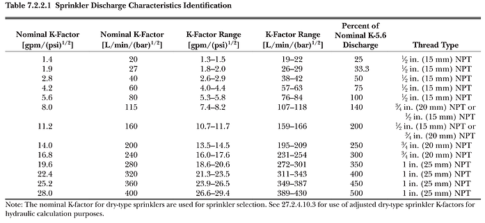
Identification: Marked with manufacturer code, K-factor, temperature rating, and sensitivity.
-
Discharge Characteristics: Sprinklers must conform to K-factor ranges (Table 7.2.2.1).
-
Special Types:
-
Residential sprinklers may use different K-factors.
-
CMSA & ESFR sprinklers have defined minimum K-factors.
-
-
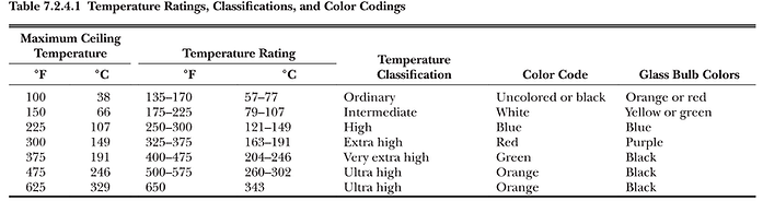
Temperature Classifications & Color Coding:
-
Ordinary: 135–170°F (57–77°C) → Orange/Red bulb
-
Intermediate: 175–225°F (79–107°C) → Yellow/Green bulb
-
High: 250–300°F (121–149°C) → Blue bulb
-
Extra High: 325–375°F (163–191°C) → Purple bulb
-
Very Extra High: 400–475°F (204–246°C) → Black bulb
-
Ultra High: 500°F+ (260°C+) → Black bulb
-
3. Piping & Tubing
-
Approved Materials (Table 7.3.1.1): ASTM/AWWA standards for steel, copper, CPVC, brass, stainless steel.
-
Identification: All pipes marked with manufacturer, size, schedule, and material.
-
Nonmetallic Pipes: CPVC permitted when listed for sprinkler use.
4. Fittings
-
Must meet ASTM/ASME standards (Table 7.4.1).
-
Types of Joints:
-
Threaded – per ASME B1.20.1.
-
Welded – full penetration welds, NFPA 51B compliance.
-
Grooved – must be compatible with couplings.
-
Brazed/Soldered – limited to copper tubing in certain occupancies.
-
-
Outlet Fittings: Must meet listing requirements, smooth bore, no modifications allowed.
5. Valves & Alarms
-
Indicating Valves: Must fully open/close within 5 seconds.
-
Waterflow Alarm Devices: Audible alarm within 5 minutes after water flow starts.
6. Additives & Coatings
-
Only listed additives for corrosion/microbial control permitted.
-
Internal pipe coatings must be approved for sprinkler use.
✅ Practical Takeaway:
Chapter 7 ensures that only tested, approved, and properly identified components are used in fire sprinkler systems. Correct materials, fittings, joining methods, and marking requirements are critical for both system performance and NFPA 13 compliance.
Chapter 8: System Types & Requirements
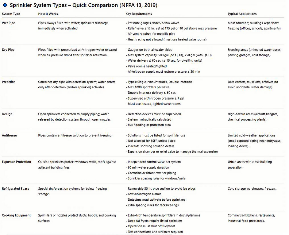
1. Wet Pipe Systems
-
Must have pressure gauges above and below each check/alarm valve.
-
Require a listed relief valve (≥ ½ in., set at 175 psi or 10 psi above max pressure).
-
Auxiliary systems (e.g., preaction, deluge) may be supplied if water supply is adequate.
-
Air vents required on metallic pipe systems to reduce corrosion.
-
Heat tracing is not acceptable in place of heated enclosures
2. Dry Pipe Systems
-
Pressure gauges required on water and air sides of the valve, at compressors/receivers, and quick-opening devices.
-
Permitted sprinkler orientations: Upright, listed dry sprinklers, pendent/sidewall on return bends (if heated), horizontal sidewall without trapped water.
-
System capacity limits:
-
Dwelling units → 15 sec. water delivery.
-
General → 60 sec. max (Table 8.2.3.6.1).
-
≤ 500 gal without QOD, ≤ 750 gal with QOD.
-
-
Quick-Opening Devices (QODs) help meet delivery time limits.
-
Dry pipe valves must be protected against freezing and mechanical damage.
-
Air/nitrogen supply must restore pressure within 30 min (60 min if refrigerated)
3. Preaction & Deluge Systems
-
Preaction types:
-
Single interlock → detection device operation.
-
Non-interlock → detection device OR sprinkler.
-
Double interlock → both required.
-
-
Max. 1000 sprinklers per preaction valve (single/non-interlock).
-
Double interlock delivery time ≤ 60 sec. or per Table 8.2.3.6.1.
-
Components must be compatible & supervised.
-
Valves and supply pipes must be in heated, lighted valve rooms.
-
Deluge systems must be hydraulically calculated
4. Combined Dry/Preaction for Piers & Wharves
-
Must function independently if either detection or sprinkler system fails.
-
Large systems (> 600 sprinklers) require parallel dry pipe valves.
-
Must deliver water within 3 minutes max.
-
Equipped with quick-opening devices
5. Antifreeze Systems
-
Solutions must be listed; not permitted for ESFR unless approved.
-
Placards required at riser and valves with solution details.
-
Expansion chambers or relief valves required to handle thermal expansion.
-
Test connections required at remote locations
6. Exposure Protection Sprinklers
-
Used for windows, walls, roofs at risk from nearby fires.
-
Must be supplied from a standard water supply or approved alternate.
-
Open or automatic sprinklers permitted.
-
Pipe/fittings must be corrosion resistant.
-
Water supply must support 60 min duration
7. Refrigerated Spaces
-
Additional requirements for dry/preaction systems in < 32°F (0°C) spaces.
-
Removable pipe sections required to prevent ice plugging.
-
Low air/nitrogen alarms required.
-
Detectors must activate before sprinklers unless double interlock.
-
Detector spacing and arrangement detailed for racks and ceilings
8. Cooking Equipment Protection
-
Sprinklers/automatic spray nozzles required in ducts, hoods, and plenums.
-
Deep fat fryers require listed sprinklers.
-
Operation must shut off all fuel and heat sources automatically.
-
Must include test connections and strainers.
-
Sprinklers in ducts/plenums must be extra high temperature rated
✅ Practical Takeaway:
Chapter 8 outlines specific requirements for each system type—wet, dry, preaction, deluge, antifreeze, exposure protection, refrigerated space systems, and cooking hazards. The focus is on ensuring water delivery times, compatibility, supervision, freeze protection, and special hazard coverage for reliable system performance.
Window Sprinklers (Chapter 8 – Section 8.7.8.4)
-
Placement:
-
Listed window sprinklers must be positioned within 2 in. (50 mm) of the top of the window sash.
-
They must be installed per their listing and Table 8.7.8.4 requirements
NFPA 13-2019 Chapter 8
.
-
-
Spacing & Protection:
-
A single line of sprinklers may protect two stories of vertically aligned windows, provided the facade is sufficiently flush for water rundown
-
If window recesses or projections are > 1 in. (25 mm), then separate sprinklers are required for each window on each level.
-
-
Discharge Requirements:
-
Window sprinklers must maintain a minimum discharge pressure of 7 psi (0.5 bar).
-
They are part of exposure protection systems that must be hydraulically calculated based on severity of exposure (Table 8.7.9.1).
-
-
Example from Table 8.7.8.4:
-
Up to 3 ft wide window → K2.8 sprinkler at 7 in. from sash.
-
5–7 ft wide window → K11.2 sprinkler at 12 in. from sash.
-
Wider windows require multiple sprinklers or higher K-factors
-
Window sprinklers are a special category of exposure protection sprinklers. They are installed close to the top of the sash and are carefully sized/spaced to provide a protective water film over glass, reducing the chance of fire spread between buildings.

Chapter 9: Sprinkler Location Requirements
1. General Positioning
-
Sprinklers must be installed at locations ensuring uniform discharge.
-
Distance from walls: comply with minimum/maximum clearances per sprinkler type.
-
Deflector orientation: positioned level unless otherwise listed.
2. Obstructions to Discharge
-
Sprinklers must be arranged so beams, ducts, lights, and structural members do not block spray.
-
Continuous obstructions > 4 ft (1.2 m) wide require sprinklers beneath them.
-
Isolated obstructions: follow clearance rules based on distance below ceiling.
-
Light fixtures: Sprinklers must be placed to ensure full spray coverage around fixtures.
3. Beams & Joists
-
Solid Beams: Sprinklers required in every bay where beams exceed certain depth (see Table).
-
Open Joists: Rules based on spacing and depth.
-
Sprinklers required under closely spaced or deep beams unless exceptions apply.
4. Ceiling Pockets, Recesses, and Cloud Ceilings
-
Ceiling pockets > 36 in. deep require sprinklers inside.
-
If ≤ 1000 ft² and depth ≤ 36 in., sprinklers may be omitted if construction meets criteria.
-
Cloud ceilings: sprinklers required both above and below unless free area is ≥ 70% and spacing criteria met.
-
Special rules for step ceilings, drops, and projections.
5. Vertical Shafts, Chutes, & Dumbwaiters
-
Sprinklers required at top and bottom.
-
If shaft has intermediate openings, sprinklers must be installed accordingly.
6. Stairways & Escalators
-
Under escalators: sprinklers required at top and bottom landings and beneath escalator if combustible.
-
Stair enclosures: sprinklers required at landings if combustible construction or required by code.
7. Ducts & Mechanical Equipment
-
Concealed duct spaces require sprinklers unless exempted.
-
Sprinklers must be installed:
-
Inside large ducts where combustible materials may accumulate.
-
Near obstructions caused by ductwork.
-
8. Concealed Spaces (Critical Section)
Sprinklers are not required in the following concealed spaces:
-
Limited combustible or noncombustible construction.
-
Noncombustible or fire-resistive insulation-filled spaces.
-
Concealed spaces < 55 ft³ in volume.
-
Noncombustible construction with minimal fuel load (e.g., steel trusses, gypsum board).
-
Certain concealed spaces under 24 in. in depth.
➡️ Note: This exemption list is heavily used in design and must be applied carefully.
9. Exterior Projections & Overhangs
-
Sprinklers required beneath combustible projections > 4 ft (1.2 m) wide.
-
Omission permitted for:
-
Noncombustible projections.
-
Fire-resistive construction.
-
Certain open-grid or ventilated canopies with ≥ 70% free area.
-
-
Loading docks and similar structures require coverage unless noncombustible.
10. Bathrooms, Closets & Small Rooms
-
Bathrooms < 55 ft² with noncombustible walls/ceilings → sprinklers may be omitted.
-
Closets < 24 ft² → omission possible under noncombustible construction and no storage of combustibles.
-
Pantries & storage rooms → sprinklers required unless construction qualifies for exemption.
11. Balconies, Decks & Exterior Spaces
-
Combustible balconies require sprinklers below unless certain construction exemptions apply.
-
Exterior decks and galleries must follow rules similar to canopies.
12. Skylights, Roof Monitors & Draft Curtains
-
Skylights > 32 ft² require sprinklers if combustible framing is present.
-
Draft curtains may affect sprinkler spacing and must be considered in layout.
-
Roof monitors: sprinklers may be needed depending on geometry and construction.
13. Special Features
-
Overhead Doors: Sprinklers required if combustible or if door assembly can obstruct discharge.
-
Ceiling Fans: Maintain required clearance to avoid spray disruption.
-
Light Fixtures: Install sprinklers to ensure spray pattern is unobstructed.
14. Window Sprinklers (Sprinkler-Protected Glazing)
-
Must use listed window sprinklers when used as fire-rated glazing alternative.
-
Key requirements:
-
Wet pipe supply only.
-
Heat-strengthened, tempered, or glass-ceramic glazing.
-
Glass must be fixed, non-load-bearing.
-
Sprinklers on both sides if protection required.
-
No horizontal members obstructing water film.
-
Water supply must last as long as fire-resistance rating of the assembly.
-
✅ Practical Takeaway:
Chapter 9 is all about placement logic and omission allowances. For consultants:
-
Always verify obstruction clearances, concealed space exemptions, and balcony/ceiling pocket conditions.
-
Document code justification when sprinklers are omitted.
-
For glazing or architectural features, confirm listing requirements and water supply duration.
Chapter 10: Standard Pendent, Upright & Sidewall Spray Sprinklers
1. General Requirements
-
Applies to standard pendent, upright, and sidewall spray sprinklers.
-
Must follow Section 9.5 location rules, unless specifically modified here
-
Quick-response sprinklers not permitted in extra hazard occupancies under density/area design method
2. Protection Area & Spacing
-
Light Hazard: max 225 ft² per sprinkler; 15 ft spacing.
-
Ordinary Hazard: max 130 ft² per sprinkler; 15 ft spacing.
-
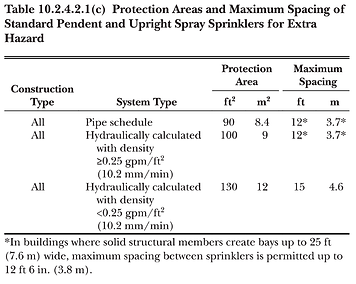
Extra Hazard: typically 90–130 ft² with spacing limits.
-
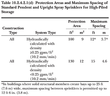
High-Piled Storage: spacing rules apply per Table 10.2.4.2.1(d).
-
Absolute max area: no sprinkler may exceed 225 ft² coverage
-
In small rooms, coverage = room area ÷ number of sprinklers
3. Wall & Spacing Distances
-
Max distance to wall = ½ allowable spacing.
-
Min distance from wall = 4 in.
-
Min spacing between sprinklers = 6 ft, unless baffles are used
-
Sprinklers allowed closer if separated by solid baffles (≥8 in. long, ≥6 in. high).
4. Deflector Positioning
-
Unobstructed ceilings: deflectors 1–12 in. below ceiling.
-
Obstructed construction: follow one of 5 placement options (e.g., in bays, within 1–6 in. of structural members, under tees).
-
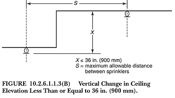
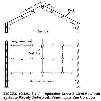
Peaked ceilings/roofs: deflectors ≤36 in. below peak.
-
Double joists: sprinklers may be required above and below.
-
Sloped ceilings (≥4:12 pitch): special placement rules apply, including quick-response sprinklers near peaks
5. Obstructions to Discharge
-
Sprinklers must avoid spray shadowing from beams, ducts, or structural members.
-
If unavoidable: additional sprinklers required.
-
Continuous obstructions ≤18 in. below deflector: require clearance or additional sprinklers.
-
Fixed obstructions >4 ft wide: sprinklers required below.
-
Under ducts or gratings: use intermediate/rack-type sprinklers or shields
6. Clearance to Storage
-
Min clearance = 18 in. between deflector and top of storage.
-
Follow stricter clearances if other standards require
7. Ceiling Pockets
-
Sprinklers are NOT required inside a ceiling pocket if all of the following conditions are met:
-
The total volume of the ceiling pocket is ≤ 1000 ft³ (28 m³).
-
The depth of the ceiling pocket is ≤ 36 in. (900 mm).
-
The entire floor area below the pocket is already protected by sprinklers at the main (lower) ceiling level.
-
If there are several ceiling pockets within the same compartment and within 10 ft (3 m) of each other, their combined total volume must still be ≤ 1000 ft³ .
-
The ceiling pocket surfaces must be finished with noncombustible or limited-combustible materials.
-
The compartment must use quick-response sprinklers throughout.
-
-
Skylights exempt if per 9.3.16.
Sprinklers can be omitted in skylights if:
-
The skylight area is ≤ 32 ft² (3 m²).
-
The frame is noncombustible.
-
The skylight does not cover a combustible concealed space.
8. Sidewall Sprinklers (Special Rules)
-
Allowed only in:
-
Light hazard (flat/sloped ceilings).
-
Ordinary hazard (flat ceilings, if listed).
-
Below overhead doors, in hoistways, for column protection, and under specific obstructions.
-
-
Coverage formula: A = S × L (S = along wall, L = across room).
-
Max area = 196 ft², max spacing along wall = 14 ft.
-
Min distance from wall = 4 in.; Min spacing = 6 ft unless baffled.
-
Deflector position: 4–6 in. below ceiling (special listings may allow 6–18 in.).
9. Small Rooms & Compartmented Areas
-
In small rooms:
-
Area of coverage = actual floor area ÷ number of sprinklers.
-
Can exceed listed spacing if room area limitation governs.
-
-
Ensures adequate coverage without exceeding design area allowance.
10. Special Applications
-
Under Overhead Doors: Sidewall sprinklers permitted to protect combustible doors.
-
Columns: Sidewall sprinklers may be installed for combustible columns.
-
Hoistways/Elevator Shafts: Sidewall sprinklers allowed where upright/pendent impractical.
-
Rack Protection: Intermediate-level sprinklers may be required at rack tiers.
-
Draft Curtains: Closely spaced sprinklers may be required at curtain edges.
11. Sloped & Irregular Ceilings
-
For sloped ceilings, spacing measured along slope.
-
Sprinkler spacing and positioning must account for heat flow path.
-
Quick-response sprinklers required in some steep slope cases to ensure fast activation.
9. Practical Keypoints for Designers
-
Always check hazard classification vs. coverage area.
-
Verify deflector heights against ceiling type (flat, sloped, peaked, obstructed).
-
Watch for obstructions (ducts, beams, fans, fixtures).
-
Maintain 18 in. clearance to storage.
-
Apply special allowances/exemptions (small rooms, skylights, ceiling pockets) carefully.
-
Use sidewalls only where permitted; check listings.
-
Document all design decisions where exceptions are applied.
✅ Practical Takeaway:
Chapter 10 provides the nuts-and-bolts installation rules for standard spray sprinklers. It expands Chapter 9’s general location criteria with exact coverage limits, deflector positions, spacing rules, and obstruction allowances. For consultants, this is the go-to checklist to avoid common design and inspection failures.


Chapter 16 – Installation of Piping, Valves, and Appurtenances
1. General Requirements
-
Piping, valves, and appurtenances must follow NFPA 13 and referenced standards.
-
All materials must be listed/approved for fire protection service.
-
Installations must prevent mechanical injury, freezing, corrosion, and allow for inspection, testing, and maintenance.
2. Piping
-
Pipe Materials: Steel, ductile iron, copper, CPVC, HDPE (if listed).
-
Pipe Joints: Threaded, grooved, flanged, welded, mechanical, restrained.
-
Ends must be cut square, reamed, and threaded per ASME B1.20.1.
-
Welding must comply with NFPA 51B and ASME Section IX; welds must be smooth, full penetration, no internal projections.
3. Underground Pipe
-
Must also comply with NFPA 24.
-
Burial depth: ≥ 30 in. (750 mm) or below frost line.
-
Restraint: thrust blocks or listed restraining devices at bends, tees, and dead ends.
-
Backfilling: First 6 in. (150 mm) must be clean, tamped earth or sand; no stones or debris.
-
Hydrostatic test: 200 psi (14 bar) or 50 psi above working pressure, held for 2 hrs.
-
Flushing velocity: ≥ 10 ft/s.
4. Aboveground Pipe Installation
-
Pipe must be supported with listed hangers and supports (see Chapter 17).
-
Pipe shall not be bent or overstressed.
-
Allow for expansion/contraction.
-
Sleeves required at walls/floors with clearance for movement.
5. Valves
-
Control Valves: Must be listed, accessible, and supervised (PIV, WPIV, OS&Y, or butterfly).
-
Post Indicator Valves (PIVs): Tops set 32–40 in. above grade; must be protected from damage.
-
Valves in Pits: Allowed if PIV impractical; pits must be large, dry, accessible, and clearly marked.
-
Check Valves: Required to prevent reverse flow; orientation must match listing.
-
Alarm Valves: Installed per manufacturer instructions.
-
Pressure-Reducing Valves (PRVs): Required where supply > 175 psi; must have gauges on both sides, relief valve downstream, and test connection.
-
Pressure-Relief Valves: Required for wet pipe systems > 175 psi.
-
All valves must be tagged/identified with function and area served.
6. Appurtenances
-
Drains:
-
Main drain at each riser.
-
Auxiliary drains at trapped sections.
-
Inspector’s test connection simulating smallest orifice (½ in. opening).
-
-
Vents: Required at system high point to reduce trapped air and corrosion risk.
-
Relief Devices: Provided as needed for overpressure protection.
-
Backflow Preventers: Installed where required by plumbing codes; must be listed and accessible.
7. Special Requirements
-
Corrosion Protection:
-
Metallic pipe must have protective coating/wrap in corrosive conditions.
-
CPVC must be shielded from UV light.
-
-
Identification: Piping must be painted or stenciled per NFPA or AHJ rules.
-
Seismic Design: Flexible couplings, restraints, and bracing required in seismic zones (see Chapter 18).
8. Testing & Acceptance
-
Hydrostatic Test (aboveground):
-
200 psi or 50 psi above system pressure, held for 2 hrs.
-
No leakage allowed.
-
-
Pneumatic Test (alternative):
-
40 psi air for 24 hrs; ≤ 1.5 psi pressure drop.
-
Soap solution leak test required.
-
-
Flushing: Required before connection to sprinklers to remove debris.
✅ Practical Takeaway:
Chapter 16 ensures that piping, valves, drains, vents, and appurtenances are properly installed, restrained, and tested. Key focus areas: approved pipe materials, correct valve supervision, thrust restraint underground, hangers/seismic bracing aboveground, drainage/venting, corrosion protection, and full acceptance testing.
Chapter 17: Hanging and Support of System Piping
1. General Rules
-
Hangers must meet NFPA 13 requirements unless designed/certified by a registered professional engineer to support:
-
5× weight of water-filled pipe plus 250 lb (115 kg) at each support point.
-
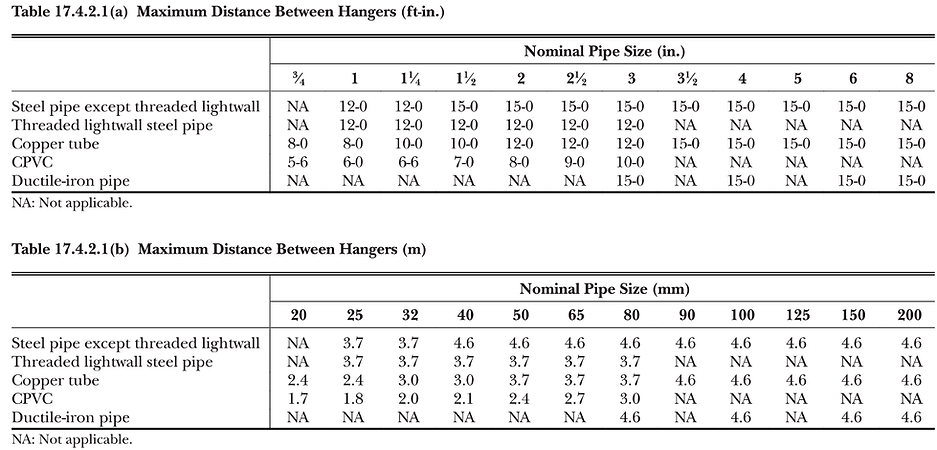
Maximum hanger spacing as per Table 17.4.2.1(a) & (b).
-
Ferrous materials only.
-
-
Piping/hangers cannot support non-system components.
-
Shared support structures allowed only if engineered and designed for sprinkler loads plus other utilities.
-
Seismic requirements: must also comply with Chapter 18 in seismic zones.
-
Hanger assemblies attaching to pipe/building must be listed, except mild steel rods and certain fasteners.
-
Hangers and components must be ferrous, unless listed/tested otherwise.
2. Hanger Components
-
Hanger Rods:
-
Minimum sizes per Table 17.2.1.1 (e.g., 3/8 in. for ≤4" pipe, 1/2 in. for 6", 5/8 in. for 10").
-
No bending/threading of rods in the field.
-
-
U-hooks & Eye Rods: Minimum sizes per tables; must include washers/lock washers when attached to wood.
-
Fasteners:
-
Concrete: use listed inserts or post-installed anchors; no use in cinder concrete/soft ceilings.
-
Steel: powder-driven or welded studs must be listed; no welding studs to thin (<12 gauge) steel.
-
Wood: lag screws, bolts, U-hooks with screws per Table 17.2.4.2.1; nails are not permitted.
-
-
Coach Screw Rods: Limited to pipe ≤4"; plank thickness and beam width must meet Table 17.2.4.7.2.
3. Trapeze Hangers
-
Must be sized per Table 17.3.1(a–c) (section modulus requirements).
-
Longer leg of angles installed vertically.
-
Slotted holes restricted in length, spacing, and number; washers/nuts required on both sides.
4. Pipe Hanger Installation
-
Piping must be supported independently of ceiling sheathing (except toggle hangers for ≤1½" pipe).
-
Hangers must attach to building structure able to support water-filled pipe + 250 lb load.
-
Flexible Sprinkler Hose Fittings: Must be installed per listing; max 6 ft unsupported length; ceiling grid must comply with ASTM C635/C636.
-
Branch line hangers attached to metal deck allowed only for ≤1" pipe with through-bolts.
-
Piping under ductwork may use duct supports only if supports handle combined loads.
5. Hanger Spacing & Locations
-
Maximum spacing per Table 17.4.2.1(a & b) (e.g., steel pipe 15 ft, copper 10–15 ft, CPVC 5.5–10 ft).
-
End sprinkler unsupported length:
-
Steel: 36" (1"), 48" (1¼"), 60" (≥1½").
-
Copper: 18" (1"), 24" (1¼"), 30" (≥1½").
-
-
Armover unsupported length:
-
Steel: 24"; Copper: 12".
-
If pressure >100 psi: Steel 12", Copper 6".
-
-
Wall-mounted sidewall sprinklers must be restrained.
-
Sprigs ≥4 ft must be laterally braced.
6. Hanger Locations on Mains
-
Hangers required between branch lines or per spacing rules.
-
Some intermediate hangers may be omitted in bays with 2, 3, or 4+ branch lines if purlin hangers provided.
-
End of mains must not exceed ½ of allowable hanger spacing unsupported.
7. Riser Supports
-
Risers supported with clamps/hangers within 24" of riser centerline.
-
Set-screw type riser clamps prohibited.
-
Multistory buildings: supports at lowest level, every other floor, above/below offsets, and top of riser.
-
Max riser support spacing: 25 ft (7.6 m).
8. Pipe Stands
-
Must support 5× water-filled pipe weight + 250 lb.
-
Components must be ferrous.
-
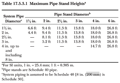
Max heights per Table 17.5.3.1 (varies by pipe size).
-
Base plates: malleable/welded steel flanges; anchored with ≥4 anchors (2 allowed for certain cases).
-
Anchors: ≥½" dia. for ≤3" pipe, ≥5/8" for ≥4" pipe.
-
Pipe attached to stand with U-bolts or equivalent; bracket offset ≤12".
-
Must restrain thrust forces from water hammer/reaction.
-
Exterior applications: galvanized/corrosion-resistant materials required.
✅ Practical Takeaway:
Chapter 17 provides detailed requirements for hangers, supports, trapeze hangers, riser clamps, and pipe stands.
Key points:
-
Always size rods and fasteners per tables.
-
Do not overload ceilings/ducts.
-
Respect unsupported length limits at end sprinklers and armovers.
-
Riser supports at every other floor.
-
Use listed hanger assemblies and corrosion-resistant materials outdoors.

Chapter 19: Design Approaches
1. General Provisions
-
Applies to all sprinkler system design approaches unless modified by Chapters 20–26.
-
Design approach may be chosen by the designer (occupancy hazard, storage, or special occupancy).
-
Water supply must meet or exceed the system demand + hose allowance for the full required duration.
2. Water Supply & Hose Allowance
-
Add inside hose demand (50–100 gpm depending on hose stations).
-
Add outside hose demand at hydrants or mains.
-
Combined systems (sprinkler + standpipe): compare NFPA 13 vs. NFPA 14 requirements — use the higher.
-
Isolated small high-hazard rooms (≤400 ft²) may be designed to principal occupancy demand.
3. Pipe Schedule Systems
-
Permitted for:
-
Additions to existing pipe schedule systems.
-
Small modifications/extensions.
-
Certain small/light hazard occupancies.
-
-
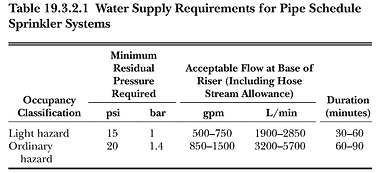
Must follow Table 19.3.2.1 (pressure and flow requirements by hazard).
-
Not permitted for new full-system designs in larger or higher hazard occupancies.
4. Hydraulically Designed Systems
-
Must be used when pipe schedule is not permitted.
-
Must consider density/area curves, room design method, or special design areas.
-
Hydraulic calculations must include sprinklers in most demanding area + hose allowance.
5. Occupancy Hazard Fire Control Approach
-
Light Hazard: offices, schools, hotels.
-
Ordinary Hazard (Group 1 & 2): manufacturing, service stations, retail.
-
Extra Hazard (Group 1 & 2): flammable liquids, woodworking, printing.
-
Special Occupancy Hazard: where unique hazards exist.
-
Must meet minimum water supply duration per hazard class (30–120 min).
6. Hydraulic Calculation Rules
-
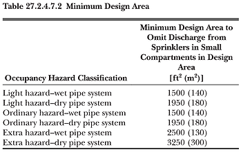
Minimum areas:
-
1500 ft² for Light/Ordinary hazard.
-
2500 ft² for Extra Hazard.
-
-
Unsprinklered combustible concealed spaces: min 3000 ft² design area.
-
Supply duration (per Table 19.3.3.1.2):
-
Light Hazard → 30 min.
-
Ordinary Hazard → 60–90 min.
-
Extra Hazard → 90–120 min.
-
7. Density/Area Method
-
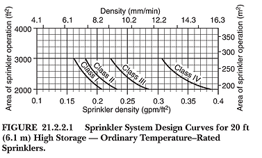
Design point must be on or above density/area curve.
-
Adjustments permitted:
-
Quick-response sprinklers: design area reduction allowed (Light/Ordinary, ≤20 ft ceiling).
-
High-temperature sprinklers: reduce design area 25% (not <2000 ft²).
-
Large K-factor sprinklers (K-11.2+): reduce design area 25% (not <2000 ft²).
-
Sloped ceilings >1:6: increase area by 30%.
-
Dry pipe/double-interlock preaction: increase area by 30%.
-
-
Minimum # of sprinklers:
-
Standard: area ÷ max coverage per sprinkler.
-
Extended coverage: min 5 sprinklers.
-
-
Adjustments must be compounded (multiplicative).
8. Room Design Method
-
Protect the room of greatest sprinkler demand.
-
Room must be enclosed with fire-rated construction equal to required water supply duration.
-
Door/opening rules:
-
Light hazard: nonrated self-closing doors acceptable.
-
Ordinary/Extra hazard: fire-rated doors required.
-
-
Corridors with single row: max 5 sprinklers or 75 ft of sprinklers in design area.
9. Special Design Areas
-
Chutes: max 3 sprinklers at ≥15 gpm each.
-
Single-line designs: max 7 sprinklers.
-
Ducts: ≥7 psi at each duct sprinkler, all flowing.
-
Stair towers: treated as one area for pipe sizing.
10. High Volume Low Speed (HVLS) Fans
-
Max diameter: 24 ft.
-
Must be centered between 4 sprinklers.
-
Vertical clearance: ≥3 ft below deflector.
-
Must shut down on waterflow alarm (interlocked to fire alarm if present).
11. Special Sprinkler Approaches
-
Residential Sprinklers:
-
Design = 4 adjacent sprinklers (8 if combustible concealed space).
-
Min density = 0.1 gpm/ft² (or higher if listed).
-
-
Exposure Protection Sprinklers:
-
≥7 psi per sprinkler.
-
Supply must handle combined demand.
-
-
Water Curtains:
-
3 gpm per linear ft; min 15 gpm per sprinkler.
-
Deluge/proscenium applications require all sprinklers flowing.
-
-
Sprinkler-Protected Glazing:
-
Supply duration = fire rating of assembly.
-
Design area includes sprinklers adjacent to glazing.
-
-
Deluge/Open Sprinkler Systems:
-
Hydraulically calculated for all open nozzles.
-
Must comply with NFPA 15 (water spray) or NFPA 750 (water mist) as applicable.
-
✅ Practical Takeaway:
Chapter 19 is the heart of NFPA 13 sprinkler design. It requires designers to:
-
Choose the right design method (pipe schedule, hydraulic, room design, or special).
-
Apply correct design area & density requirements.
-
Add hose demands correctly.
-
Adjust design areas for special conditions (slopes, QR, high-temp, dry/preaction).
-
Follow rules for special applications (residential, exposure, glazing, curtains, deluge).


Chapter 21: Control Mode Density/Area (CMDA) Sprinklers
1. Scope of Chapter 21
-
CMDA sprinklers = the traditional density/area method for fire control.
-
Their purpose is control, not suppression (unlike ESFR).
-
Chapter 21 applies when protecting:
-
Class I–IV commodities (solid pile, palletized, racks, shelving).
-
Some plastic commodities (limited).
-
Idle pallet storage.
-
-
If hazard exceeds CMDA limits → must use CMSA (Ch. 20) or ESFR (Ch. 23).
2. General Design Rules
-
Base design on density (gpm/ft²) × design area (ft²).
-
Use density/area curves from Chapter 19 or the storage tables in Chapter 21.
-
Must add hose stream allowance.
-
Apply area adjustments (same as Ch. 19):
-
Dry/preaction systems → +30% design area.
-
Sloped ceiling >1:6 → +30% design area.
-
Quick-response sprinklers → design area reduction (Light/Ordinary hazards only).
-
High-temperature sprinklers → −25% design area (not <2000 ft²).
-
Large K-factor sprinklers (≥K-11.2) → −25% design area (not <2000 ft²).
-
-
Minimum sprinklers:
-
Standard CMDA: area ÷ max coverage per sprinkler.
-
Extended coverage CMDA: at least 5 sprinklers in design area.
-
3. Commodity Classification (foundation for CMDA design)
-
Class I–IV commodities:
-
Class I = essentially noncombustible with minimal packaging.
-
Class II = Class I with some combustible packaging.
-
Class III = Class I/II or free-flowing Group C plastics, paper, wood.
-
Class IV = Class I–III with higher packaging combustibility or Group B plastics.
-
-
Plastics:
-
Group A plastics = most challenging (CMDA use restricted).
-
Group B plastics = moderate.
-
Group C plastics = least hazardous.
-
4. CMDA for Solid Pile & Palletized Storage
-
CMDA permitted up to certain storage heights (typically ≤12–15 ft under ceilings ≤25 ft).
-
Density/area curves in Chapter 21 specify:
-
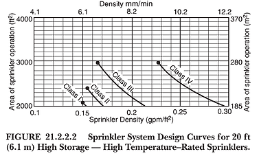
Class I–IV → design density around 0.15–0.30 gpm/ft² depending on ceiling height.
-
Higher hazards → higher density required.
-
-
Beyond permitted height → must add in-rack sprinklers or switch to CMSA/ESFR.
5. CMDA for Rack Storage
-
Open racks: CMDA ceiling-only protection allowed only for low heights (Class I–IV, usually ≤12–15 ft storage).
-
Double-row racks: CMDA allowed up to limits (beyond that, in-rack sprinklers required).
-
Multiple-row racks: CMDA ceiling-only not permitted above certain heights.
-
Solid shelving racks: always require in-rack sprinklers due to no vertical heat venting.
-
Plastics in racks:
-
CMDA limited for Group A plastics — usually requires CMSA/ESFR.
-
6. CMDA for Shelving Storage
-
Open shelving: treated similar to racks, with CMDA up to height limits.
-
Solid shelving: requires in-rack sprinklers (fire cannot vent upward).
7. CMDA for Idle Pallet Storage
-
Idle pallets pose very high challenge (high surface area, air circulation).
-
CMDA allowed up to 6 ft storage height.
-
For higher stacks, in-rack sprinklers or CMSA/ESFR required.
8. Design Area Adjustments (specific emphasis in Ch. 21)
-
Dry pipe / double-interlock preaction → +30% area.
-
Sloped ceiling (>1:6) → +30% area.
-
Quick response sprinklers (Light/Ordinary only) → area reduction allowed.
-
High-temperature sprinklers → −25% area (but not <2000 ft²).
-
Large K-factor sprinklers → −25% area (not <2000 ft²).
-
Multiple adjustments are compounded.
9. Water Supply Duration
-
Must follow Chapter 19 durations unless Chapter 21 tables specify longer.
-
Typical minimums:
-
Light hazard → 30 min.
-
Ordinary hazard → 60 min.
-
Extra hazard → 90–120 min.
-
Storage occupancies (especially Class III/IV) often require 60–90 min duration.
-
10. CMDA vs. Other Sprinklers (decision rules)
-
Use CMDA if:
-
Commodity = Class I–IV.
-
Storage ≤15 ft and ceiling ≤25 ft.
-
Tables in Ch. 21 give applicable density.
-
-
Must use CMSA or ESFR if:
-
Storage >15 ft or ceilings >25–30 ft.
-
Group A plastics in racks.
-
Solid shelving racks above low heights.
-
Idle pallets above 6 ft.
-
11. Engineer’s Checklist
-
Identify commodity class (I–IV, plastics).
-
Identify storage type (pile, palletized, rack, shelving, idle pallets).
-
Verify storage height and ceiling height.
-
Check Chapter 21 tables for permitted CMDA densities/areas.
-
Add hose stream allowance.
-
Apply adjustments (dry pipe, sloped, QR, high-temp, large K).
-
Ensure min # of sprinklers in design area.
-
For racks/shelving: confirm if in-rack sprinklers are required.
-
Confirm supply duration meets Chapter 19 or storage rules.
-
If outside CMDA limits → design using CMSA (Ch. 20) or ESFR (Ch. 23).
✅ Practical Takeaway:
Chapter 21 is where traditional density/area CMDA sprinklers meet storage occupancies. It gives you the limits and allowances for using CMDA in warehouses, racks, and pallet storage. But the designer must be very careful: if the commodity, storage height, or arrangement exceeds CMDA limits → you must switch to CMSA or ESFR.


Chapter 25: Protection of Rack Storage Using In-Rack Sprinklers
1. General Requirements
-
Applies to rack storage of Class I–IV commodities, Group A plastics, and rubber tires
-
Systems must be designed for open rack configurations unless stated otherwise.
-
System size limit: Max 40,000 ft² floor area (including aisles) per in-rack system.
-
Control valves:
-
Separate valves for in-rack and ceiling sprinklers unless ≤ 20 in-rack sprinklers per ceiling system.
-
Sectional control valves allowed for ≤ 8,000 ft² areas.
-
-
Waterflow alarm: Required for in-rack sprinklers.
-
Building steel: No special protection required when in-rack sprinklers are installed.
2. Ceiling-Level Sprinkler Design (with In-Rack Sprinklers)
-
Criteria vary for miscellaneous, low-piled, CMDA, CMSA, and ESFR systems
-
Miscellaneous storage (≤ 12 ft high): Use OH2 design area (NFPA 13 Table 19.2).
-
Low-piled racks: Similar rules; add in-rack sprinklers for solid shelves.
-
CMDA ceiling designs:
-
Class I–IV over 12–25 ft → refer to detailed density/area tables.
-
Group A plastics over 5–25 ft → stricter densities and in-rack requirements.
-
Rubber tires over 12 ft → min 0.40 gpm/ft² density (or reduced to 0.24 with foam).
-
-
CMSA ceiling designs: Higher K-factors (K-11.2, K-16.8). Preaction = dry.
-
ESFR ceiling designs: Must supplement with at least one level of in-rack sprinklers, using Table 25.2.5.1.1.
3. In-Rack Sprinkler Characteristics
-
Types: Upright or pendent, standard or quick-response.
-
Nominal K-factors: 5.6, 8.0, or 11.2.
-
Quick-response required if ceiling is ESFR.
-
Must use water shields (unless protected by horizontal barriers).
-
Temperature ratings: Ordinary unless near heat sources.
4. Vertical Spacing & Location
-
Minimum 6 in. clearance between deflector and top of storage.
-
If one level required → install at half storage height.
-
If two levels required → install at one-third and two-thirds of height.
-
Max storage above top in-rack level: 10 ft.
5. Horizontal Location & Spacing
-
Spacing rules depend on rack depth and aisle width.
-
In general, sprinklers must be placed to protect all flue spaces.
-
Special layouts required for double-row and multiple-row racks.
6. Racks with Solid Shelves
-
In-rack sprinklers required at each tier with solid shelving.
-
Water shields or horizontal barriers must be provided.
7. Horizontal Barriers
-
May be used with in-rack sprinklers to limit fire spread.
-
Must be noncombustible or limited-combustible.
-
Installed above sprinkler heads unless listed otherwise.
8. Independent In-Rack Sprinkler Systems
-
Permitted to design independent of ceiling sprinklers.
-
Must meet density/area criteria within Chapter 25.
-
Still subject to hydraulic calculations.
9. In-Rack + CMDA Ceiling Sprinklers
-
Specific density/area tables given for Class I–IV and plastics.
-
Adjustments:
-
Additional tiers allow 20–40% density reductions.
-
Above 25 ft → stricter rules, max 10 ft clearance above top tier.
-
10. In-Rack + CMSA Ceiling Sprinklers
-
Use Table 25.2.4.2.1 (Class I–IV) and Table 25.2.4.3.1 (Plastics).
-
Requires higher minimum operating pressures.
-
Preaction = dry classification.
11. In-Rack + ESFR Ceiling Sprinklers
-
One level of in-rack required for Class I–IV and plastics.
-
Ceiling density/pressure from Table 25.2.5.1.1.
-
Design area = 12 sprinklers (4 on 3 branch lines).
12. Design Criteria & Hydraulic Considerations
-
Hose stream allowance from Table 20.12.2.6 must be added.
-
Hydraulic design must satisfy density/area curves in Ch. 25.
-
Min density = 0.15 gpm/ft² after adjustments.
-
Duration per Chapter 20 requirements.
Chapter 27: Plans and Calculations
1. Working Plans – General
-
Must be submitted to the Authority Having Jurisdiction (AHJ) before installation, addition, or remodeling.
-
Electronic submittals are permitted if accepted by AHJ.
-
A copy of approved plans must be provided to the owner/representative.
-
Deviations from approved plans are not permitted unless resubmitted and approved.
2. Required Information on Plans
Working drawings must show at least:
-
Owner, occupant, project name, and building address.
-
Point of compass, scale, and graphical reference.
-
Floor plans and building cross-sections showing:
-
Ceiling construction and heights.
-
Roof slopes, partitions, fire walls/barriers.
-
Occupancy of each area.
-
Locations of concealed spaces, attics, bathrooms, closets.
-
Unprotected spaces (must be clearly noted).
-
-
Water supply information:
-
City main size, location, whether dead-end or circulating.
-
Flow test results (static, residual, flow, date, and who conducted).
-
Elevation of building relative to test hydrant.
-
Other water supplies (tanks, pumps, reservoirs).
-
-
Sprinkler data:
-
Manufacturer, model, SIN, K-factor, orifice size, temperature rating, response type.
-
Coverage area and locations.
-
Number of sprinklers on each floor and in each system.
-
-
Pipe information:
-
Sizes, lengths, materials, schedule/wall thickness.
-
Type of joints (threaded, welded, grooved, mechanical).
-
Risers, riser nipples, hangers, braces, fittings, weld locations.
-
-
Valves and devices:
-
Control, check, alarm, preaction, deluge, pressure-reducing, and pressure-relief valves (manufacturer and model).
-
Backflow preventer location + forward flow test connection.
-
-
Alarms and hose:
-
Local bells, water motor gongs, flow switches.
-
Hose outlets, standpipes, hydrants, fire department connections.
-
-
Other:
-
Piping arrangements for flushing.
-
Seismic bracing, loads, and zones of influence.
-
Hydraulic reference points and calculation nodes.
-
Density/area, hose stream allowances, total pressure and flow required.
-
Antifreeze solution details (type and amount).
-
Pressure-reducing valve settings.
-
Year/edition of NFPA 13 used for design.
-
3. Owner’s Certificate
-
Must be signed by the owner or owner’s representative.
-
Describes occupancy, hazards, and protection objectives.
-
Must accompany working plan submittals.
-
Include manufacturer’s installation instructions for any specially listed devices.
4. Special Plans (Non-Fire Connections)
-
If system connects to non-fire equipment (pumps, exchangers, strainers), plans must:
-
Show auxiliary piping clearly and separately.
-
Use unique symbols.
-
Include make, model, and manufacturer of devices.
-
5. Plan Certification
-
Some jurisdictions require working plans and calcs to be signed/sealed by a licensed Professional Engineer (PE) or NICET Level III/IV in fire protection engineering technology.
-
Certification ensures professional accountability.
6. Hydraulic Calculation Procedures
-
All new systems (except pipe schedule exceptions) must be hydraulically calculated.
-
Small modifications/extensions may remain pipe schedule (see Section 13 below).
-
Pipe size minimums:
-
1 in. steel.
-
¾ in. copper, brass, stainless, CPVC, or other nonmetallic.
-
-
Flow velocity is not limited if Hazen-Williams or Darcy-Weisbach is applied.
-
Calcs extend to the effective water supply point (usually nearest hydrant/test point).
7. Formulas & Methods
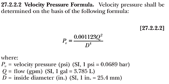
-
Hazen–Williams formula for most water systems.
-
Darcy–Weisbach required when antifreeze > 40 gallons (viscosity correction).
-
Velocity pressure must be included.
-
Junction balance: pressure difference between parallel paths ≤ 0.5 psi.
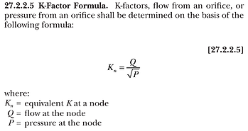
-
Sprinkler discharge = K × √P (K-factor equation).
8. Equivalent Pipe Lengths
-
Table of fitting/valve losses (elbows, tees, crosses, reducers) → convert to equivalent pipe length.
-
Riser nipples and couplings included.
-
Must use listed friction loss data if available for specific fittings/valves.
9. Design Area Methods
-
Density/Area Method:
-
Design area shaped as rectangle ≥ 1.2√A.
-
Must include sprinklers on both sides of a cross-main.
-
-
CMSA Method:
-
Based on max coverage area per sprinkler.
-
Same 1.2√A shape rule applies.
-
-
ESFR Method:
-
Fixed to 12 sprinklers (4 sprinklers × 3 branch lines).
-
-
Gridded Systems:
-
Must prove the most demanding area.
-
At least two remote areas must be calculated unless software can demonstrate system peaking.
-
-
Room Design Method:
-
Entire communicating space must be included.
-
Room must be enclosed by fire-rated construction equal to water supply duration.
-
10. Friction Loss & Pressures
-
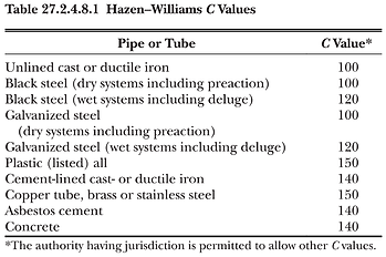
Hazen–Williams C-values per Table 27.2.4.8.1 (differs by pipe material/age).
-
Must include friction through fittings, tees, riser nipples.
-
PRVs: must use manufacturer’s listed pressure loss data.
-
Orifice plates are not permitted as balancing devices.
-
Min sprinkler pressure = 7 psi (ordinary sprinklers).
-
Storage sprinklers (CMSA/ESFR) may require ≥15 psi at K-25.2 or higher.
-
Max system pressure = 175 psi (unless sprinklers listed for higher).
11. In-Rack Sprinklers (Hydraulic Considerations)
-
Piping to in-rack sprinklers must be sized by hydraulic calcs.
-
In-rack demand must be added to ceiling demand at point of connection, then balanced to whichever pressure is higher.
12. Hose Stream Allowance
-
Outside hose allowance added at city main or nearest hydrant.
-
Inside hose allowance added at riser or system demand point.
-
Must comply with Chapter 19 allowance tables.
13. Hydraulic Calculation Forms & Reports
Each calc package must include:
-
Summary sheet: hazard, density/area, total system demand, hose allowance, duration.
-
Graph sheet: plot water supply curve and overlay system demand + hose allowance.
-
Supply analysis: static pressure, residual pressure, flow at residual.
-
Node analysis: node elevations, K-factors, flows, and pressures.
-
Detailed worksheets: pipe lengths, diameters, equivalent lengths, friction loss, pressure at nodes.
-
Grid calcs: diagram showing flow distribution, supply node, and pressure balance.
-
Safety margin: not mandated by NFPA, but many AHJs require showing 10% or 5 psi surplus at residual.
14. Pipe Schedule Systems (Permitted Cases Only)
-
Generally superseded by hydraulic calculations.
-
Still permitted for:
-
Existing systems.
-
Small new systems/additions in light or ordinary hazard occupancies.
-
-
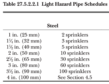
Pipe schedules (Table 27.3.2.2 & 27.3.2.3):
-
Light Hazard: ≤8 sprinklers per branch line on 1 in. pipe (can extend to 9–10 with 1¼ in. pipe).
-
Ordinary Hazard: ≤8 sprinklers per branch line on 1¼ in. pipe.
-
End branch lines, ceiling heights, and spacing affect allowed counts.
-
-
Extra Hazard occupancies must be hydraulically calculated.
✅ Practical Takeaway:
Chapter 27 is the administrative + technical backbone of NFPA 13:
-
It tells you what must appear on drawings and calcs,
-
how to do the math (Hazen–Williams, Darcy–Weisbach, C-values),
-
how to combine demands (in-rack + ceiling + hose),
-
and when pipe schedule is still allowed.