
IS 15105:2021 – Fire Sprinkler Design Standard (India)
Design, Installation and Maintenance of Fixed Automatic Sprinkler System
IS 15105:2021 is the Indian Standard issued by the Bureau of Indian Standards (BIS) that specifies the minimum requirements for the design, installation, and maintenance of fixed automatic sprinkler systems in buildings.
This standard applies to sprinkler systems used for the protection of life and property across a wide range of occupancies, including industrial, commercial, residential, and storage buildings.
Scope of the Standard
The standard covers:
-
Design criteria for sprinkler systems
-
Installation requirements
-
Hydraulic calculation methods
-
Water supply and pumping capacity requirements
-
Hazard classification of occupancies
-
Storage commodity categorization
-
Requirements for high-rise buildings
-
Guidelines for ESFR, Large Drop, and in-rack sprinklers
-
Documentation and drawing requirements
-
Maintenance provisions to ensure system reliability
The provisions are applicable to:
-
New installations
-
Additions or extensions to existing sprinkler systems
-
Modifications or repairs to installed systems
What is NOT Covered
This standard does not apply to:
-
Water spray systems
-
Deluge systems (covered under IS 15325 and IS 15519)
-
Marine, aircraft, vehicle or mining sprinkler applications
Design Philosophy
IS 15105 emphasizes:
-
Proper hazard classification (Light, Ordinary, High, Storage)
-
Hydraulic calculation for high hazard systems
-
Enhanced storage protection requirements
-
Adoption of modern sprinkler technologies such as ESFR
-
Integration of sprinkler systems with overall fire protection strategy
The 2021 revision strengthens hydraulic design requirements and aligns Indian practice closer to international standards.
🔥 Types of Sprinklers

Alarm Valve
An alarm valve is a specially designed check valve installed in a sprinkler system that allows water to flow into the system when a sprinkler operates and simultaneously initiates an alarm signal.
When water flows through the valve due to sprinkler activation, it operates an alarm device such as:
-
A water motor gong (mechanical alarm), and/or
-
An electric pressure switch connected to the fire alarm system.
Each type of sprinkler system (wet, dry, deluge, pre-action) incorporates a suitable alarm valve arrangement to ensure that water flow during fire conditions is automatically detected and signaled.
The alarm valve also permits system monitoring through upstream and downstream pressure gauges and includes provisions for alarm testing.

Main Elements of a Sprinkler Installation

🔹 Key Components
-
Installation Control Valve Set
Includes the alarm valve and stop valve. It controls water supply to the sprinkler system and initiates alarm when water flows. -
Main Distribution Pipe (Feed Main)
Primary pipe that distributes water to different distribution pipes. -
Distribution Pipe (Cross Main / Destination Pipe)
Supplies water to branch (range) pipes. -
Range Pipe (Branch Pipe)
Pipes feeding individual sprinklers directly or through arm pipes. -
Arm Pipe
Short pipe (generally less than 300 mm) connecting range pipe to sprinkler head. -
Riser
Vertical pipe supplying water to upper levels. -
Sprinkler Head
Heat-activated device that discharges water when fire is detected. -
Design Point
Reference point used in hydraulic calculations (especially in pre-calculated systems). -
Drain Valve with Plug
Used for draining and testing the system.
🔹 Working Principle (Simple Flow Path)
Water Supply → Control Valve Set → Main Distribution Pipe → Distribution Pipe → Range Pipe → Sprinkler Head
When a sprinkler operates, water flows through the alarm valve, triggering an alarm.
Range Pipe Arrays in Sprinkler Systems
The figure shows different configurations of range (branch) pipes connected to distribution pipes in a sprinkler installation. These layouts affect hydraulic performance and water distribution.

1️⃣ 2- End-Side Array (Central Feed)
-
Range pipes provided on one side only of the distribution pipe.
-
Water fed from central point.
-
Used in narrow areas or where layout is restricted.
2️⃣ 3-End-Side Array (End Feed)
-
Range pipes on one side.
-
Water supply connected at one end of distribution pipe.
-
Simpler layout but higher friction loss at far end.
3️⃣ 3-End-Centre Array (Central Feed)
-
Range pipes on both sides of distribution pipe.
-
Supply from centre.
-
More hydraulically balanced.
-
Common in large open floor areas.
4️⃣ 2-End-Centre Array (End Feed)
-
Range pipes on both sides.
-
Supply from one end.
-
Requires careful hydraulic calculation for pressure drop.
Engineering Importance
-
Layout selection impacts:
-
Hydraulic calculations
-
Pressure loss
-
Number of operating sprinklers
-
Design area performance
-
-
End feed systems generally require higher pressure at remote points.
-
Central feed systems provide better pressure balance.
Sprinkler Network Layouts
This figure illustrates different sprinkler spacing patterns and piping network arrangements used in sprinkler system design.

3A – Rectangular Matrix Layout
-
Sprinklers arranged in straight rows and columns.
-
Equal spacing in both directions.
-
Most commonly used layout.
-
Easy for hydraulic calculations.
-
Suitable for standard hazard occupancies.
S = Distance between sprinklers in one direction
D = Distance between sprinklers in the other direction

3C – Looped Layout
-
Cross mains interconnected.
-
Water can reach sprinklers from more than one direction.
-
Reduces pressure loss.
-
More hydraulically reliable than simple tree systems.

3B – Staggered Layout
-
Alternate rows offset by half spacing.
-
Provides more uniform water distribution.
-
Improves coverage efficiency.
-
Often used where better spray overlap is required.

3D – Gridded Layout
-
Branch lines interconnected forming grid pattern.
-
Water supplied from multiple paths.
-
Provides best hydraulic balance.
-
Suitable for large floor plates and high hazard areas.
Engineering Significance

Requirements Regarding Documentation
IS 15105 specifies that proper drawings and documentation must be submitted for approval before installation of a sprinkler system.
General Drawing Requirements
-
Drawings must be clear, dated, and to scale.
-
Scale generally: 1:500 or 1:1000 (site plans).
-
For installation layout: not less than 1:100.
-
Digital copies are acceptable if approved.
-
Drawings must show:
-
Entire compound
-
All buildings
-
Future extensions (if any)
-
Boundary walls
-
Details to be Shown on Drawings
Building Information
-
Fire walls, fire doors, shutters
-
Construction type (masonry, steel, etc.)
-
Floor areas and elevations
-
Ceiling heights
-
Concealed spaces
Sprinkler System Details
-
Complete sprinkler layout
-
Pipe sizes and routing
-
Type of sprinklers
-
Temperature rating
-
K-factor
-
Number of sprinklers per control valve
-
Height of highest sprinkler
-
Location of alarm valves
-
Drain valves and test valves
Water Supply Details
-
Pump capacity and head
-
Pump house layout
-
Suction and delivery piping
-
Water tank capacity and compartmentation
-
Overflow and freeboard levels
-
Electrical supply to fire pumps
Hydraulic Calculation Requirements
For Fully Hydraulic Systems, documentation must include:
-
Design density (mm/min)
-
Design area (m²)
-
Assumed Maximum Area of Operation (AMAO)
-
Sprinkler K-factor
-
Flow through each sprinkler
-
Pressure at each node
-
Pipe sizes
-
Pipe lengths
-
Equivalent lengths of fittings
-
Hazen-Williams coefficient
-
Static head changes
-
Friction loss calculations
-
Pressure-flow graph of water supply
Mandatory Declaration
A statement confirming:
The system complies with IS 15105:2021, including any deviations with justification.
Why Documentation is Important
-
Ensures regulatory approval
-
Verifies hydraulic balance
-
Confirms adequate water supply
-
Provides reference for maintenance
-
Prevents under-designed systems


PLANNING STAGE
The planning stage ensures proper integration of the sprinkler system with building design, water supply, and other fire protection measures.
1️⃣ Initial Considerations

2️⃣ Outline Design Considerations

3️⃣ Interaction with Other Fire Protection Systems

4️⃣ Extent of Sprinkler Protection

5️⃣ Exceptions (Where Sprinklers May Not Be Required)

Planning Stage – Key Objective
✔ Correct hazard classification
✔ Adequate water supply
✔ Proper integration with building design
✔ Avoid conflicts with other fire systems
✔ Ensure long-term maintainability
Protection of Concealed Spaces

Height Difference Between Highest & Lowest Sprinklers

SPRINKLERS – General Requirements
1️⃣ General Provisions

2️⃣ Selection of Sprinklers
Sprinklers shall be selected based on:
-
Occupancy hazard classification
-
Storage configuration (if applicable)
-
Ceiling height
-
Type of sprinkler system (wet, dry, etc.)
-
K-factor requirements
-
Temperature rating
3️⃣ Installation Requirements
-
Sprinklers must be installed in correct orientation (pendent/upright/sidewall).
-
Installed as per spacing and positioning rules of the standard.
-
Must comply with approved listing and manufacturing standards.
-
Only listed sprinklers for special applications (e.g., concealed spaces) shall be used.
4️⃣ K-Factor Requirement


Selection of Temperature Rating for Sprinklers
Sprinklers operate when the thermal element reaches its rated temperature. The correct temperature rating must be selected based on the maximum expected ambient ceiling temperature.

Typical Selection Guidance

Temperature Rating for High Piled Storage
1️⃣ High Hazard – High Piled Storage

2️⃣ Glazed Roof or PVC / Plastic Roofing Sheets

3️⃣ Near Ovens or Hot Process Hoods

4️⃣ Clearance from Hot Sources
Because sprinklers are heat sensitive:
-
Must be located minimum 750 mm to 2000 mm away from hot sources
-
Distance depends on ambient temperature conditions
🔥 Key Engineering Insight
High piled storage produces:
-
Rapid fire growth
-
High ceiling jet temperatures
Therefore:
✔ Higher temperature rating prevents premature activation
✔ Ensures correct sequence of sprinkler operation
✔ Avoids unnecessary system discharge
Mixing of Different Types of Sprinklers
🔹 General Rule
Different types of sprinklers shall not be used in the same hazard area, unless specifically justified and approved.
Mixing different sprinkler characteristics can result in:
-
Uneven water distribution
-
Hydraulic imbalance
-
Improper fire control performance
🔹 The Following Shall Be Avoided

🔥 Engineering Principle
A sprinkler system must operate as a uniform hydraulic and thermal unit.
Mixing types within the same hazard area may cause:
-
Delayed suppression
-
Over-discharge in some areas
-
Under-protection in remote areas
Protection to the Sprinklers
🔹 General Requirement
Sprinklers shall be installed and protected so that their operation, discharge pattern, and sensitivity are not impaired by mechanical damage, corrosion, or environmental conditions.
🔹 Mechanical Protection

🔹 Corrosion Protection

🔹 Installation Protection
-
Sprinklers shall not be obstructed.
-
Guards or protective devices shall not interfere with water distribution.
-
Only manufacturer-approved protective devices shall be used.
🔥 Objective of Clause 7.9
✔ Ensure sprinkler reliability
✔ Prevent accidental damage
✔ Maintain proper spray performance
✔ Preserve thermal sensitivity
Spare Sprinklers to be Kept in Stock
A stock of spare sprinkler heads shall be maintained on the premises to enable prompt replacement of operated or damaged sprinklers.


Design Area and Density of Application
1️⃣ Light Hazard (LH)

2️⃣ Ordinary Hazard (OH)

🔸 Storage in OH Occupancy (Allowed Only If):

📦 Maximum Storage Heights in OH (Table 6)

3️⃣ High Hazard (HH)

4️⃣ Storage Hazard
Density depends on:
- Sprinkler type selected
- Flow & pressure requirements
Typical Density Range: 25 – 50 lpm/m²
Refer to Annex C for detailed design criteria.
Buildings Like Residential, Hotels & Similar

🔥 Quick Comparison Table

Engineering Insight
-
Density = Fire control capability
-
Design Area = Assumed Maximum Area of Operation (AMAO)
-
Density shall never be reduced even if actual compartment is smaller
-
Storage design is significantly more demanding
Design Area and Density of Application
This clause defines how the design area is determined when using special types of sprinklers.
1️⃣ Extended Coverage (EC) Sprinklers

2️⃣ Large Drop (LD) Sprinklers

3️⃣ ESFR Sprinklers

4️⃣ Intermediate (In-Rack) Sprinklers

🔥 Engineering Insight
-
EC sprinklers → Larger spacing → Larger design area
-
Large Drop → Control mode → Rectangular demand area
-
ESFR → Fixed 12-sprinkler calculation
-
In-rack → Based on rack geometry & aisle width
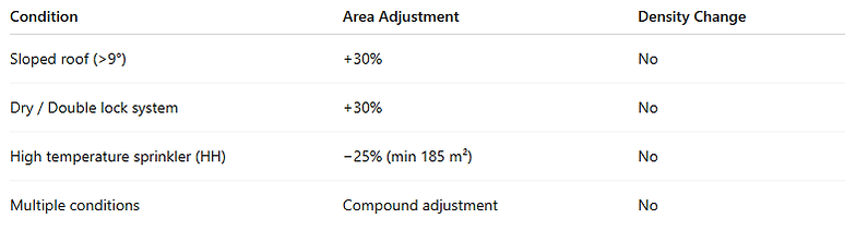
Adjustment in Area of Operation (Design Area)
This clause specifies when the design area (AMAO) must be increased or reduced based on system and building conditions.
1️⃣ Sloping Roofs

2️⃣ Dry Pipe & Double Lock Pre-Action Systems

3️⃣ High Temperature Sprinklers (High Hazard)

4️⃣ Multiple Adjustments
If more than one condition applies:
-
Adjustments shall be compounded
-
Based on original design area specified in 8.1
Example:
If both sloping roof and dry system apply →
Area = Base Area × 1.3 × 1.3
5️⃣ Concealed Spaces
-
Concealed spaces (combustible or non-combustible) follow the same adjustment rules
-
Exception: If concealed space area < 5 m², adjustment not required
🔥 Quick Summary Table
Engineering Insight
-
Area adjustment compensates for:
-
Slower activation
-
Water delivery delay
-
Ceiling jet behavior changes
-
Thermal lag in high temperature sprinklers
-
Density remains unchanged — only the assumed operating area is modified.
Water Curtain Sprinklers
Water curtain sprinklers are used to create a water barrier (blanket effect) across openings to prevent fire spread between compartments.
🔹 Performance Requirements

🔹 Design Considerations
Water curtain sprinklers are typically:
-
Open type nozzles
-
Used for fire separation
-
Installed over openings
Water supply for curtain sprinklers:
-
Shall be added to main system demand
-
As per Clause 13 (Water Supply Requirements)
🔹 Important Notes

Engineering Purpose
Protect openings between compartments
✔ Prevent horizontal fire spread
✔ Provide water shield across glass walls or large openings
✔ Used where fire walls are not feasible
Exposure Protection
Exposure protection sprinklers are used to protect building surfaces (such as glass walls or openings) from fire exposure originating from adjacent structures or areas.
🔹 General Requirements

🔹 Protection Limits

🔹 Glass Wall Protection

🔹 Window & Similar Openings

Sprinklers Provided in Ducts

Window Sprinklers
Window sprinklers are specially listed sprinklers used for interior protection of windows or glazing and for exposure protection.

Design Approach – Spacing, Location and Installation
🔷 Key Design Considerations
Clause 9 lays down the fundamental principles for the layout, spacing, positioning, and installation of sprinklers to ensure effective fire control and uniform water distribution.

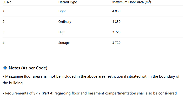
🔷 Maximum Area to be Covered by Sprinklers
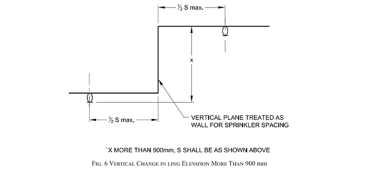
🔷 Vertical Change in Ceiling Elevation (Less Than 900 mm)


🔷 Vertical Change in Ceiling Elevation (Less Than 900 mm)
🔷 Sprinklers Below Obstructions
Sprinklers Below Ducts
Sprinklers shall be installed below ducts in the following situations:
-
Where ducts are rectangular and more than 0.8 m wide, and located less than 150 mm from adjacent walls or partitions.
-
Where ducts are circular and more than 1 m in diameter, and located less than 150 mm from adjacent walls or partitions.
-
Where ducts are rectangular and more than 1 m in width.
-
Where ducts are circular and more than 1 m in diameter.
Movable Obstructions
Sprinklers are not required under movable obstructions such as:
-
Conference tables
-
Similar movable furniture
Hoods Over Paper Making Machines
Sprinklers shall be installed:
-
Under hoods or shields
-
Over dry ends of paper making machines
-
Where an enclosure exists
Worktables
Sprinklers shall be installed below worktables:
-
Where a power source exists, or
-
Where combustible process waste may accumulate
(Applicable to industrial and storage occupancies only.)
Important Note
Sprinklers installed below obstructions shall be of the same type as the ceiling sprinklers.
🔷 Sprinkler Location Below Ceilings

🔷 Positioning of Sprinklers to Avoid Obstruction to Discharge


🔷 Standard Sidewall Sprinklers
🔹 Protection Area

🔹 Maximum Distance Between Sprinklers
-
Spacing shall be measured along the slope of the ceiling.
-
Maximum spacing:
-
4.3 m for Light Hazard
-
3.0 m for Ordinary Hazard
-
-
Sidewall sprinklers shall not be installed back-to-back unless separated by a continuous lintel or soffit.
-
They may be installed on opposing or adjacent walls provided no sprinkler exceeds its permitted protection area.
-
When installed on two opposite walls or sides of bays:
-
Maximum room width: 7.3 m (High Hazard)
-
6.1 m (Ordinary Hazard)
-
🔹 Minimum Distance Between Sprinklers
-
Minimum centre-to-centre spacing: 1.8 m
-
Distance from wall shall be measured perpendicular to the wall.
🔹 Maximum Distance from Walls
-
End sprinklers shall not exceed half of the allowable distance between sprinklers.
🔹 Minimum Distance from Walls
-
Minimum distance from wall: 100 mm
-
Distance measured perpendicular to the wall.
🔹 Minimum Distance from Walls
-
Install to minimize obstruction.
-
Lighting fixtures within 1.2 m may require additional sprinklers.
-
Clearance from top of storage (if any): 450 mm minimum.
-
Sidewall sprinklers in rooms shall be installed above window or door openings where applicable.
-
Distance between sprinkler and ceiling:
-
Not more than 150 mm (normally)
-
May increase to 450 mm where necessary
-
-
Horizontal sidewall sprinklers:
-
Not more than 100 mm below ceiling
-
Not more than 100 mm from wall
-
-
Deflectors shall be aligned parallel to ceilings or roofs.
-
On sloped ceilings (1 in 6), install at high point to discharge down slope.
🔹 Soffit Conditions
-
If soffit width/projection exceeds 200 mm, additional sprinklers shall be installed below soffit.
-
If soffit width/projection is within 200 mm, additional sprinklers are not required, subject to deflector distance compliance.
🔥 Engineering Insight
Sidewall sprinklers:
✔ Provide wall-mounted protection
✔ Suitable for corridors, small rooms, hotels
✔ Require stricter spacing control than standard pendent/upright
✔ Sensitive to obstructions and ceiling configuration
🔷 Sprinkler Location in Relation to Obstructions (Facing Across the Wall)


🔷 Sprinkler Location in Relation to Obstructions (Along the Same Wall)


🔹 Interpretation
-
Minimum horizontal clearance from obstruction must be at least 100 mm.
-
As horizontal distance (A) increases, required vertical clearance (B) also increases.
-
These values apply specifically to sidewall sprinklers when obstruction is located along the same wall.
🔷 Extended Sidewall Sprinklers
🔹 Protection Area

🔹 Maximum Distance Between Sprinklers
-
Spacing shall be measured along the slope of the ceiling.
-
Maximum spacing:
-
8.5 m (Light Hazard)
-
7.3 m (Ordinary Hazard)
-
-
Sidewall sprinklers shall not be installed back-to-back without separation by a continuous lintel or soffit.
-
May be installed on opposing or adjacent walls provided no sprinkler exceeds its maximum protection area.
🔹 Minimum Distance Between Sprinklers
-
Minimum spacing: 1.8 m centre-to-centre
-
Distance from wall measured perpendicular to wall.
🔹 Maximum Distance from Walls
-
End sprinklers shall not exceed ½ of allowable spacing.
🔹 Minimum Distance from Walls
-
Minimum distance from wall: 100 mm
-
Measured perpendicular to wall.
🔹 Sprinkler Deflector Location and Orientation
Installation Requirements
-
Deflectors shall be located to minimize obstructions.
-
Lighting fixtures within 1.2 m may require additional sprinklers.
-
Clearance from storage top to deflector: 450 mm minimum.
-
Sidewall sprinklers shall not be installed:
-
Above grills of air conditioner, or
-
Within 450 mm of the same wall.
-
-
Distance between sprinkler and ceiling:
-
Not more than 150 mm
-
May increase to 450 mm if specifically approved.
-
-
Vertical sidewall sprinklers:
-
Not more than 150 mm above or
-
Not less than 100 mm below the wall from which they discharge.
-
-
Horizontal sidewall sprinklers:
-
Not more than 100 mm below ceiling
-
Not more than 100 mm from wall.
-
-
Deflectors aligned parallel to ceilings or roofs.
-
On sloped ceilings (1 in 6), install at high point to discharge down slope.
🔹 Soffit Conditions
-
If soffit width/projection exceeds 200 mm, additional sprinklers required below soffit.
-
If soffit width/projection ≤ 200 mm, additional sprinklers not required (subject to deflector distance compliance).
🔷 Extended Coverage (EC) Sprinklers (Upright & Pendent)
🔹 Usage Restriction
-
Extended Coverage (EC) sprinklers shall not be used for buildings with combustible construction.
🔹 Protection Area & Maximum Spacing
-
Protection area shall not be less than the manufacturer’s listing and shall not exceed the following:

🔹 Minimum Distance Between Sprinklers
-
Minimum spacing: 2.4 m centre-to-centre
🔹 Maximum Distance from Walls
-
Distance from sprinkler to wall shall not exceed ½ of allowable spacing (as per Table 14).
-
Distance measured perpendicular to wall.
🔹 Maximum Distance from Walls
-
Minimum distance: 100 mm
🔹 Sprinkler Deflector Location & Orientation
General Requirements
-
Distance between deflector and ceiling:
-
Minimum 25 mm
-
Maximum 300 mm
-
Not applicable for recessed or flush sprinklers.
-
Clearance from top of storage block:
-
Not less than 450 mm
-
Deflectors shall be aligned parallel to ceilings or roofs.
🔥 Engineering Insight
Extended Coverage Sprinklers:
✔ Cover larger areas than standard sprinklers
✔ Reduce number of sprinklers in LH & OH occupancies
✔ Require larger minimum spacing (2.4 m)
✔ Highly sensitive to obstruction rules
✔ Not permitted in combustible construction
🔷 Large Drop (LD) Sprinklers
🔹 Protection Area

🔹 Maximum Distance Between Sprinklers

🔹 Minimum Distance Between Sprinklers
-
Minimum spacing: 2.4 m centre-to-centre
🔹 Maximum Distance from Walls
-
Distance from sprinklers to walls shall not exceed ½ of allowable spacing (as per 9.21.2).
🔹 Minimum Distance from Walls
-
Minimum distance from wall: 100 mm
🔹 Deflector Location and Orientation
Ceiling Clearance
-
Distance between deflector and ceiling:
-
Maximum 150 mm
-
Maximum 300 mm for buildings without obstructions
-
Orientation
-
Deflectors shall be aligned parallel to ceilings or roofs.
Obstruction Rules
-
Sprinklers shall be located to minimize obstruction to discharge.
-
If required, additional sprinklers shall be provided to ensure adequate coverage.
-
Obstruction positioning shall comply with Table 16 (refer Fig. 7).
-
For obstructions less than 600 mm wide, and located below deflector, sprinklers shall be arranged so that obstructions are centered between adjacent sprinklers.
-
If conditions are not satisfied, additional sprinklers shall be installed below the obstruction.
Storage Clearance
-
Minimum 900 mm clearance between deflector and top of storage.
🔥 Engineering Insight
Large Drop Sprinklers:
✔ Designed for higher discharge density
✔ Used in high hazard and storage applications
✔ Lower spacing than standard sprinklers
✔ Require larger minimum spacing (2.4 m)
✔ Sensitive to obstruction and storage clearance
🔷 Early Suppression Fast Response (ESFR) Sprinklers
🔹 Protection Area

🔹 Maximum Distance Between Sprinklers

🔹 Minimum Distance Between Sprinklers
-
Minimum spacing: 2.4 m centre-to-centre
🔹 Maximum Distance from Walls
-
Distance from sprinklers to walls shall not exceed ½ of allowable spacing.
🔹 Minimum Distance from Walls
-
Minimum distance from wall: 100 mm
🔹 Deflector Orientation and Location

🔹 Draught or Smoke Curtains
-
Curtains shall be treated as boundaries.
-
Sprinklers shall be located accordingly.
🔹 Range Pipes (Separation from Standard Sprinklers)
-
If ESFR and standard sprinklers are at same ceiling height:
-
Provide smoke curtains.
-
Locate curtains at mid-point between systems.
-
-
Maintain 1.2 m wide clear aisle between ESFR and standard sprinkler zones.
🔹 Range Pipes (Separation from Standard Sprinklers)
-
Range pipes shall not exceed 100 mm in size.
🔹 Other Important Requirements
-
ESFR installations accepted only where:
-
Storage roof slope ≤ 9°
-
Used below firmly secured false ceilings (slope < 9°)
-
Constructed with non-combustible construction
-
-
Wet pipe systems only.
-
Annex C shall be used for high challenge storage areas.
🔥 Engineering Insight
ESFR Sprinklers:
✔ Designed for suppression (not control mode)
✔ No in-rack sprinklers generally required
✔ Strict ceiling height & obstruction rules
✔ Require large K-factors (K-200 to K-360)
✔ Wet system only
🔷 Intermediate or In-Rack Sprinklers


🔹 Area Protection Limit
-
Area protected by a single system of sprinklers shall not exceed 3 700 m² of floor area occupied by racks.
-
Includes aisles.
-
Regardless of number of levels of in-rack sprinklers.
🔹 When In-Rack Sprinklers Are Mandatory
-
Mandatory where:
-
High hazard storage in racks, shelves, etc.
-
Storage height exceeds 4 m
-
🔹 Location Requirements
-
Sprinklers shall:
-
Not be obstructed by racks or structural steel.
-
Be located in path of longitudinal flue space.
-
-
Discharge water must penetrate stored goods.
🔹 Clearance from Stored Goods
-
Clearance between sprinkler deflectors and stored goods:
-
Minimum 150 mm
-
-
Horizontal spacing:
-
1.8 m for Category I & II goods
-
3 m for Category III & IV goods
-
-
Laterally (back-to-back racks):
-
Sprinklers on both sides required if back-to-back configuration.
-
🔹 Vertical Spacing
-
Vertical spacing between in-rack sprinklers:
-
Maximum 3 m
-
-
For fire sprinklers (roof/ceiling):
-
Not required if protected with intermediate sprinklers.
-
🔹 Location Between Horizontal & Vertical Spacing
-
Spacing between horizontal & vertical spacing shall not exceed:
-
9 m² for Category I & II goods
-
3 m² for Category III & IV goods
-
🔹 Roof/Ceiling Design Density
-
Minimum density:
-
10 lpm/m²
-
Over area of operation 260 m²
-
-
Applies where ceiling sprinklers support in-rack protection.
🔹 Maximum Number Per Control Valve
-
Where more than 50 intermediate sprinklers are installed in racks:
-
They shall not be fed from same control valve as roof sprinklers.
-
🔹 Hydraulic Calculation Assumptions

🔹 Pressure Requirements
-
Minimum and maximum pressure at operating sprinkler:
-
As per Clause 10.5.7
-

📌 Important Note
Where higher minimum operating pressure is specified for the desired application in the rules (see Clause 10.5.8), that higher pressure shall govern.
🔥 Engineering Insight
In-Rack Sprinklers:
✔ Used for high challenge storage
✔ Required when storage > 4 m
✔ Critical for flue space protection
✔ Strict clearance (150 mm) from stored goods
✔ Often used with roof sprinklers
🔷 Sprinkler Protection for Specific Areas and Hazards
🔹 Film and Television Production Studios
Sprinklers shall be fitted:
-
Under solid or slotted platforms (except temporary platforms used for sets, etc.).
-
If ceiling > 0.8 m wide and contains stairs for lighting access and lighting equipment.
-
In concealed spaces or cavities more than 100 mm deep between combustible linings and walls/roofs.
🔹 Theatres and Similar Premises
In addition to roof/ceiling sprinklers:
-
Sprinklers shall be fitted:
-
Under the grid.
-
At the flies.
-
Under stage areas.
-
Below any obstruction to discharge.
-
-
Applicable for:
-
Stage fires.
-
Moving sets.
-
Areas where personnel work near sprinklers.
-
🔹 Electronic Data Processing, Telephone Exchanges and Similar Areas
-
Sprinkler protection shall comply with provisions of IS 12456.
-
Pre-action sprinkler systems are recommended to minimize water discharge impact.
🔹 Lifts, Hoistways and Machine Rooms
a) Lift Pits
-
Sidewall sprinklers required at bottom of each lift hoistway.
-
Installed not more than 600 mm above floor of pit.
-
Not required in enclosed non-combustible lift shafts without combustible hydraulic fluids.
b) Lift Machine Rooms
-
Temperature rating: minimum 57°C, maximum 107°C.
-
Sprinkler type: pendent, upright or sidewall.
c) Lift Hoistways
-
Sprinklers required at top and bottom where lift uses:
-
Polyurethane-coated belt.
-
Similar combustible belt material.
Note:
Sprinklers in lift pit protect against fires from accumulated debris.
Lift fire-rated door guards extending below door opening shall not interfere with sprinkler discharge.
🔹 Closets and Pantries
Sprinklers required in closets and pantries (residential/hotel) when:
-
Area > 2.5 m²
-
Short dimension > 1 m
-
Walls and ceilings surfaced with combustible materials
🔹 Duct Protection
a) Vertical Risers
-
One sprinkler at top of each vertical riser.
-
One sprinkler at mid-point of each riser.
b) External Risers
-
Not required if riser located outside building and > 7.5 m from hood outlet.
c) Horizontal Exhaust Ducts
-
Sprinklers every 3 m, starting from 1.5 m from duct entrance.
d) Kitchen Exhaust Ducts
-
Shall be protected against freezing.
e) Accessibility
-
Sprinklers inside ducts shall be accessible for inspection, testing, and maintenance.
Note:
Refer Clauses 6.2.3 & 6.2.4 for protection of electrical panels, DG sets, battery rooms, UPS units, etc., when located in sprinklered occupancy.
🔥 Engineering Insight
Clause 9.24 focuses on:
✔ Special hazard spaces
✔ Concealed spaces
✔ Lift and machine rooms
✔ Duct and exhaust protection
✔ Small room exemptions (closets/pantries)
Frequently Asked Questions – IS 15105:2021 Fire Sprinkler Standard
🔥 General Questions
1️⃣ What is IS 15105:2021?
IS 15105:2021 is the Indian Standard for the design and installation of fixed automatic sprinkler systems in buildings. It covers hazard classification, design density, spacing, hydraulic calculation, storage protection, special sprinkler types, and installation requirements.
2️⃣ Is IS 15105 mandatory in India?
Yes. IS 15105 is commonly referenced by:
-
State Fire Departments
-
NBC (National Building Code)
-
Insurance authorities
-
Industrial compliance audits
It forms the basis of sprinkler system approval in India.
3️⃣ What types of sprinkler systems are covered in IS 15105?
The standard covers:
-
Wet pipe systems
-
Dry pipe systems
-
Pre-action systems
-
Deluge systems
-
Special systems (ESFR, Large Drop, In-Rack, Extended Coverage)
🏢 Hazard Classification
4️⃣ How are occupancies classified in IS 15105?
Occupancies are classified as:
-
Light Hazard (LH)
-
Ordinary Hazard (OH)
-
High Hazard (HH)
-
Storage Hazard
Each classification determines spacing, density, and area of operation.
5️⃣ What is Light Hazard occupancy?
Light hazard includes areas with low combustibility and fire load such as:
-
Offices
-
Schools
-
Hospitals
-
Residential buildings
Minimum density: 2.25 lpm/m²
6️⃣ What is Ordinary Hazard occupancy?
Ordinary hazard includes:
-
Commercial kitchens
-
Workshops
-
Small manufacturing units
-
Light industrial areas
Minimum density: 5 lpm/m²
7️⃣ What is High Hazard occupancy?
High hazard includes:
-
Process plants
-
Warehouses with combustible storage
-
Chemical storage areas
Minimum density: 12.2 lpm/m²
📐 Design Area & Density
8️⃣ What is design area (area of operation)?
Design area is the assumed maximum area over which sprinklers operate during a fire for hydraulic calculation.
Typical values:
-
LH: 84 m²
-
OH: 360 m²
-
HH: 260 m²
9️⃣ Can design area be adjusted?
Yes. Design area increases by:
-
30% for sloping roofs (> 1 in 6)
-
30% for dry pipe systems
-
May reduce by 25% for high temperature sprinklers (minimum 185 m²)
📏 Spacing & Location
🔟 What is the maximum spacing between sprinklers?
Standard sprinklers:
-
Light Hazard: 4.5 m
-
Ordinary Hazard: 4.5 m
-
High Hazard: 3.75 m
1️⃣1️⃣ What is the minimum spacing between sprinklers?
-
Standard: 1.8 m
-
ESFR / Large Drop / EC: 2.4 m
1️⃣2️⃣ What is the minimum distance from wall?
-
Minimum: 100 mm
-
Maximum: Half of allowable spacing
1️⃣3️⃣ What is the allowable ceiling deflector distance?
Depends on ceiling type:
-
Combustible ceiling: 75–300 mm
-
Non-combustible ceiling: 75–450 mm
🏗 Construction & Ceiling
1️⃣4️⃣ What is combustible construction?
Buildings where structural elements (roof, truss, beams) are made of combustible materials like wood or plastic.
1️⃣5️⃣ What is unobstructed construction?
Construction without beams or structural members that interfere with sprinkler discharge pattern.
🧯 Special Sprinklers
1️⃣6️⃣ What is ESFR sprinkler?
Early Suppression Fast Response (ESFR) sprinklers:
-
Used for high piled storage
-
High K-factor
-
Suppression mode
-
Wet system only
1️⃣7️⃣ When are in-rack sprinklers required?
Required when:
-
Storage height exceeds 4 m
-
High hazard rack storage present
1️⃣8️⃣ What is Extended Coverage (EC) sprinkler?
EC sprinklers cover larger areas (up to 37.2 m²).
Not permitted in combustible construction.
1️⃣9️⃣ What is Large Drop sprinkler?
Large Drop sprinklers:
-
Used for storage protection
-
Higher droplet size
-
Strict obstruction rules
-
Minimum spacing: 2.4 m
🏬 Storage Protection
2️⃣0️⃣ What is minimum clearance between sprinkler and storage?
-
Standard storage: 450 mm
-
Large Drop / ESFR: 900 mm
2️⃣1️⃣ What is flue space in rack storage?
Flue space is the vertical and longitudinal gap between stored goods allowing water penetration and fire control.
2️⃣2️⃣ What is maximum rack area per sprinkler system?
Maximum floor area per system: 3,700 m²
💧 Hydraulic Design
2️⃣3️⃣ What is minimum sprinkler discharge pressure?
-
Light Hazard: 0.7 bar
-
Ordinary Hazard: 0.5 bar
-
High Hazard: 0.5 bar
-
In-rack (K-115): 1.0 bar
Whichever is higher between density requirement and minimum pressure.
2️⃣4️⃣ What is maximum height difference allowed?
Maximum difference between highest and lowest sprinkler: 45 m
2️⃣5️⃣ How many sprinklers are assumed in hydraulic calculation?
Depends on hazard and type.
For in-rack: Assume 3 sprinklers operating per level (maximum 3 levels).
🚪 Special Areas
2️⃣6️⃣ Are sprinklers required in lift pits?
Yes. Sidewall sprinkler within 600 mm of pit floor (except non-combustible enclosed shafts without hydraulic fluid).
2️⃣7️⃣ Are sprinklers required in ducts?
Yes, depending on:
-
Duct size
-
Location
-
Type (vertical or horizontal exhaust)
2️⃣8️⃣ Are sprinklers required in closets?
Yes, if:
-
Area > 2.5 m²
-
Short dimension > 1 m
-
Combustible lining present
📋 Documentation & Planning
2️⃣9️⃣ What drawings are required for sprinkler approval?
-
Hydraulic calculation
-
Pipe sizing
-
Sprinkler layout
-
Hazard classification report
-
Water supply details
-
Pump capacity
3️⃣0️⃣ Can different types of sprinklers be mixed?
No. Different:
-
K-factors
-
Temperature ratings
-
RTI values
-
Spacing requirements
shall not be mixed in same hazard area.