
Automatic Sprinkler System Design Rules
Automatic sprinkler systems are life safety and property protection systems that must be designed in strict accordance with recognized standards such as NFPA 13. Proper sprinkler design is not limited to selecting pipe sizes or placing sprinkler heads; it requires systematic evaluation of building hazard classification, sprinkler spacing, hydraulic demand, zoning, and installation requirements. The following sprinkler design rules summarize the fundamental principles used in professional fire protection engineering practice, based on NFPA 13 provisions and practical hydraulic design experience.
DESIGN RULE #11: Zone (Floor) Control Stations – ZCV
Zone Control Valves (ZCVs), also called Floor Control Stations, are used to divide a building’s sprinkler system into manageable zones.
Each zone can be:
-
Independently isolated
-
Monitored
-
Tested
-
Controlled during fire events
This improves safety, maintenance efficiency, and operational reliability in multi-floor or large-area buildings.

Zone Control Stations serve three primary functions:
1️⃣ Isolation
ZCVs allow isolation of a specific floor or zone:
-
For maintenance
-
During testing
-
When modifications are required
-
To isolate damage during an emergency
Instead of shutting down the entire building, only one zone is affected.
2️⃣ Monitoring
Each zone valve is typically equipped with:
-
Supervisory switch (monitors valve position)
-
Water flow switch (detects sprinkler activation)
The status is connected to the fire alarm control panel, ensuring:
-
Valve tamper detection
-
Real-time flow monitoring
-
Immediate alarm response
3️⃣ Fire Control
During a fire:
-
The flow switch detects water movement
-
Alarm signal is transmitted
-
Only the affected zone activates
This prevents unnecessary system discharge in other areas.

A typical Zone Control Station includes:
✔ Control Valve (Butterfly or Gate Valve)
-
Controls water supply to the zone
-
Equipped with supervisory switch
-
Must normally remain open
✔ Water Flow Switch
-
Detects water movement in the zone
-
Activates fire alarm system
✔ Test & Drain Valve
-
Simulates sprinkler activation
-
Used for periodic testing
-
Drains water during maintenance
✔ Pressure Gauges
-
Installed upstream and downstream
-
Monitor system pressure
-
Help detect blockages or valve issues
Each component ensures both operational control and code compliance.
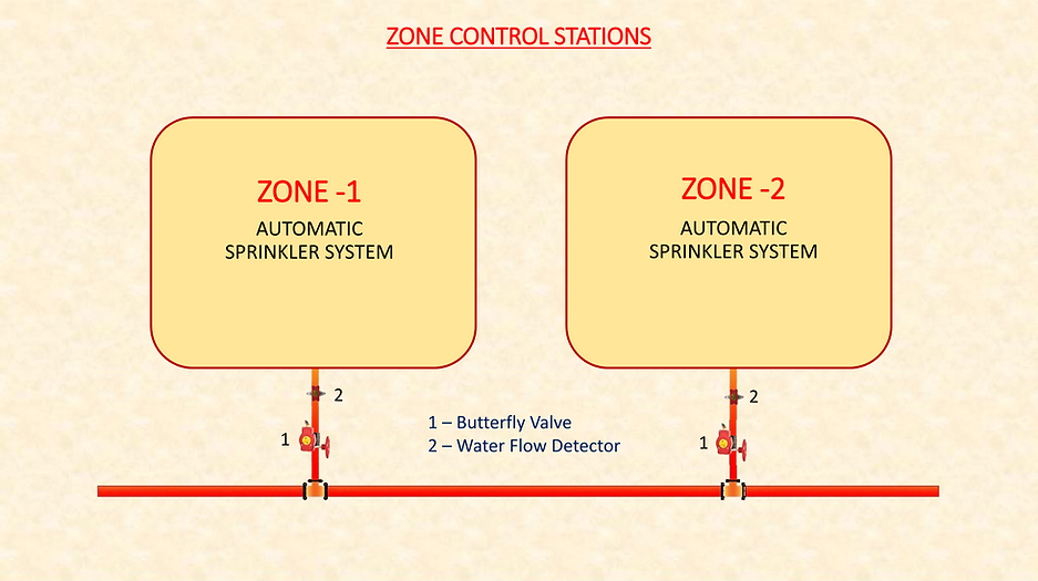
Large buildings are divided into multiple sprinkler zones.
Example:
-
Zone 1 – Floor 1
-
Zone 2 – Floor 2
-
Separate valve assemblies for each
Each zone connects to the main riser but operates independently.
This design ensures:
-
Reduced shutdown impact
-
Easier fault detection
-
Better fire location identification
-
Improved system management
Engineering Considerations
When designing ZCV locations:
-
Provide easy access (not hidden above ceilings)
-
Clearly label zone coverage
-
Ensure drain line connection
-
Coordinate with fire alarm contractor
-
Maintain proper pressure gauge visibility
In high-rise buildings, floor control stations are typically required for each floor.
⚠ Common Design Mistakes
❌ Installing ZCV in inaccessible locations
❌ Missing supervisory switch wiring
❌ Not providing drain connection
❌ Poor zone labeling
❌ Combining too large an area into one zone
Summary:
✔ ZCV divides sprinkler system into manageable zones
✔ Allows isolation, monitoring, and fire control
✔ Includes valve, flow switch, test & drain, pressure gauges
✔ Connected to fire alarm panel
✔ Essential for multi-floor and large buildings
Zone Control Stations improve safety, maintenance efficiency, and system reliability.